Detection device and detection method

a detection device and detection method technology, applied in the field of detection devices and detection methods, can solve the problems of low measurement accuracy, difficulty in utilizing -tas in the optical detection method employing conventional, and low integration, and achieve high integration, high precision, and easy production

Inactive Publication Date: 2010-09-21
CANON KK
View PDF18 Cites 0 Cited by
  • Summary
  • Abstract
  • Description
  • Claims
  • Application Information

AI Technical Summary

Benefits of technology

[0009]The present invention intends to provide a detection device which is useful for high-precision measurement of various data regarding a fluid and is miniaturized and highly integrated, and which can be produced readily with high precision. The present invention intends also to provide a detection method employing a μ-TAS with the aforementioned detection device.
[0025]According to the present invention, the state of an examination object in an examinationexamination flow channel can be detected by causing an interaction between an examinationexamination flow channel and a reference flow channel through an interaction film, and detecting deflection of an examination light introduced to the reference flow channel to determine the interaction degree. The device of the present invention does not require movement of the detection unit, and does not employ a tube which is complicated in production, so that the constitution is simple and the production cost of the device is low.

Problems solved by technology

However, it is difficult to utilize the μ-TAS in the optical detection method employing conventional device constituted usually of a flow channel of about 10 cm long and 5 mm wide because of liability to insufficiency of measurement accuracy and response speed.
In other words, the complicated constitution employed in the conventional detection device hinders realization of high integration, the feature of the μ-TAS.
Electrical measurement by the μ-TAS, for example, is liable to be affected by an electric noise, resulting in a low measurement accuracy.
On the other hand, with an examination-objective fluid diluted to avoid the drop of the S / N ratio, the signal itself becomes weak to retard difficult the measurement with a high S / N ratio.
Measurement by optical focus detection employs necessarily a beam analyzer in a large size of tens of centimeters, which is not suitable for the μ-TAS.
Detection with a simple PD conducts detection of light intensity at plural positions by moving the PD along the beam, which makes complicated the constitution to hinder miniaturization and high degree of integration even with the μ-TAS.
Such a tube cannot readily be prepared, and will be of a high production cost, and may makes troublesome the handling and operation.

Method used


Image

  • Detection device and detection method
  • Detection device and detection method
  • Detection device and detection method

Examples


first embodiment

[0047]A first embodiment of the present invention is a concentration detection device of a GRIN prism system employing asymmetric flow channels. Firstly, the basic constitution is explained of the concentration detection device of this embodiment.

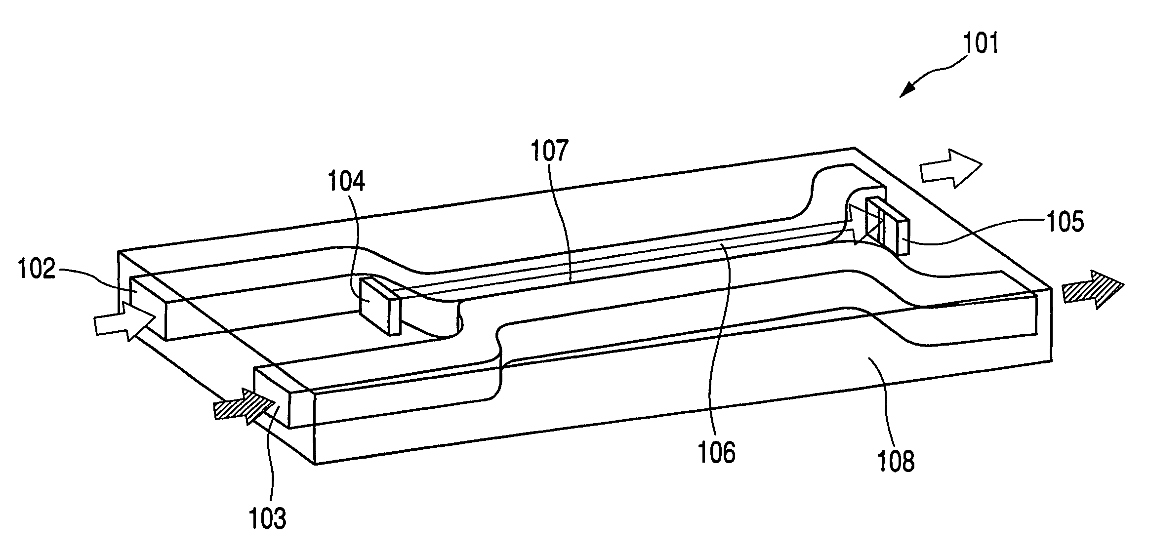
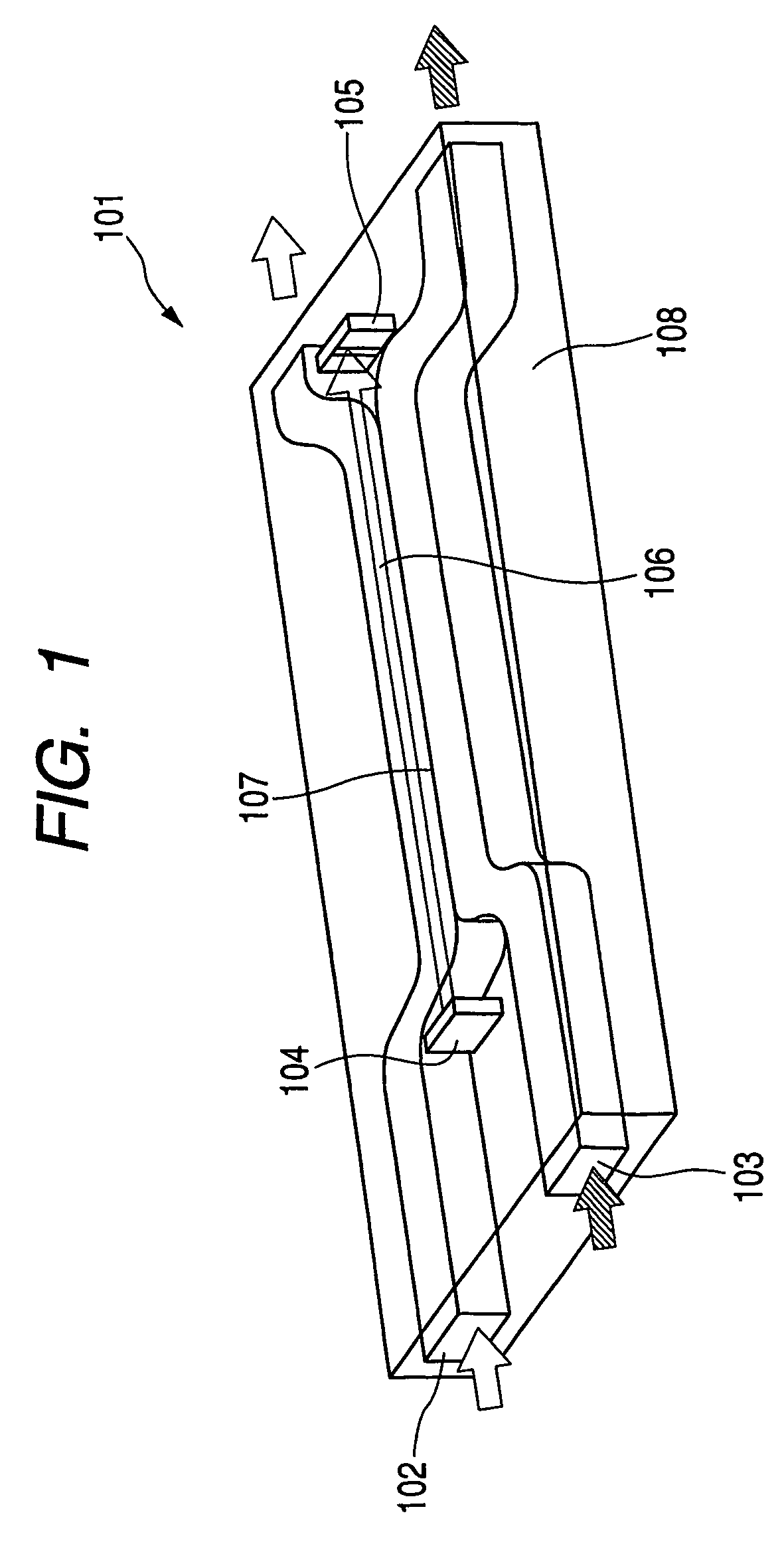
[0048]FIG. 1 is a perspective view illustrating schematically the concentration detection device of this embodiment consisting of a plate-shaped functional module 101. This functional module 101 is used for determination of a concentration of an examination-objective substance in a fluid to be examined. Functional module 101 has reference flow channel 102, and examination flow channel 103 for flow of the examination-objective fluid. The widths of the flow channels range from 10 μm to 100 μm. Reference flow channel 102 and examination flow channel 103 are partitioned with semipermeable membrane 107. Therefore, the semipermeable membrane constitutes the wall between the adjacent flow channels, whereby a substance can permeate through semiperm...

second embodiment

[0065]A second embodiment is explained below by reference to FIGS. 6 and 7. In FIGS. 6 and 7, the same members as in First Embodiment are denoted by the same symbols without explanation.

[0066]The detection device of this Embodiment, as shown in FIG. 6, similarly as First Embodiment, is provided with reference flow channel 401 and examination flow channel 402 with interposition of semipermeable membrane 107; detection light 407 is allowed to pass through reference flow channel 401; and the transmitted detecting light is received by two photodiodes 411, 410 of a two-division sensor to detect the differential signal.

[0067]The detection device of this Embodiment is constituted characteristically of a light-emission unit (not shown in the drawing), flow channel portion 408, and detection unit 409 as separate modules respectively connected in series. To avoid interference between the introduction and the discharge of the fluid to or from flow channels 401, 402 in the serial connection, in...

third embodiment

[0071]A third embodiment of the present invention is explained below by reference to FIGS. 8 and 9A to 9D. In FIGS. 8 and 9A to 9D, the same members as in First and Second Embodiments are denoted by the same symbols without explanation.

[0072]The detection device of this Embodiment comprises one reference flow channel 601, and two examination flow channels 602, 603 placed on the both sides of the reference channel with interposition of semipermeable membrane 107 respectively. Detecting light 604 is allowed to pass through reference flow channel 601, and the differential signal is detected by receiving detecting light 604 by two photodiodes 605, 606 of a two-division sensor.

[0073]In this Embodiment, different examination-objective fluids are allowed to flow through upper examination flow path 602 and lower examination flow path 603 on the both sides of reference flow channel 601. Thereby, the concentration distributions of the detection-objective substances in reference flow channel 6...


PUM

PropertyMeasurementUnit
widthaaaaaaaaaa
widthsaaaaaaaaaa
concentrationaaaaaaaaaa

Abstract

A detection device is provided which comprises an examination flow channel for passing a fluid containing a detection object, a reference flow channel extending adjacently along the examination flow channel, an interaction film interposed between the examination flow channel and the reference flow channel for causing an interaction thereof, a light emission unit for injecting a detecting light into the reference flow channel, and a detection unit for receiving the detecting light. This device is used for recognizing the state of the detection object in the examination flow channel from deflection of the optical path of the detecting light caused by the interaction.

Description

TECHNICAL FIELD[0001]The present invention relates to a detection device and a detection method employing a micro total analysis system (μ-TAS) for detecting a fine distribution of pressure or temperature, for determining a concentration of a substance, or for obtaining biological information or genetic information contained in a fluid, or the like of a fluid flowing through a flow channel in a system.BACKGROUND ART[0002]Various types of detection devices have been developed for obtaining various data of a fluid by passing an objective fluid through a detection flow channel in the device. The detection devices include electrical detection devices for measuring the concentration or temperature of an objective substance in a fluid, and optical detection devices for measuring the concentration of an objective substance in a fluid. Known optical detection devices include concentration detection devices which introduce detecting light from a light source into a fluid, measure a quantity ...

Claims


Application Information

Patent Timeline
Patent Type & Authority Patents(United States)
IPC IPC(8): B01L3/00G01N21/05G01N21/41G01N21/53G01N21/59G01N21/85G01N37/00
CPCG01N21/41G01N21/532G01N21/59G01N21/85
Inventor SUGITA, MITSURO
Owner CANON KK
Why Eureka
Try Eureka