

Pressure sensor
a pressure sensor and sensor technology, applied in the field of pressure sensors, can solve the problems of thermal distortion of the components of the sensor, inducing an error in the measured pressure value, and degradation of the characteristics of the pressure sensor, and achieves the effects of high sensitivity, good yield, and small siz
- Summary
- Abstract
- Description
- Claims
- Application Information
AI Technical Summary
Benefits of technology
Problems solved by technology
Method used
Image

Examples
first embodiment
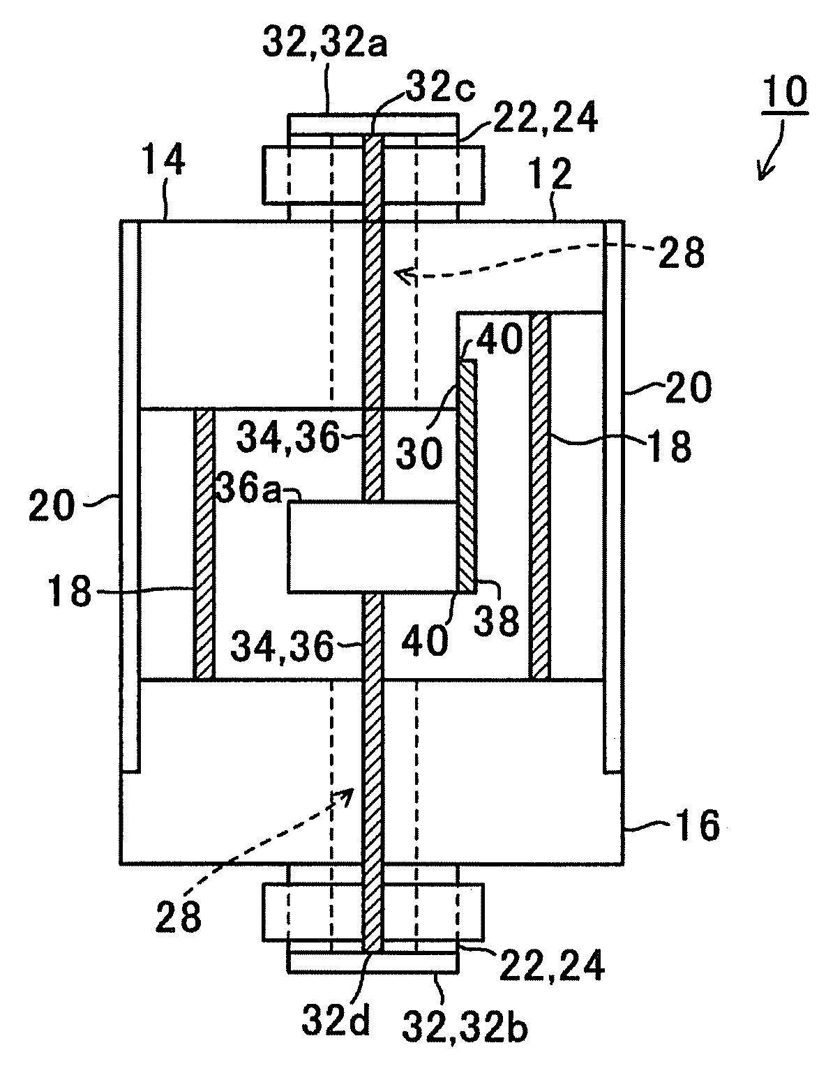
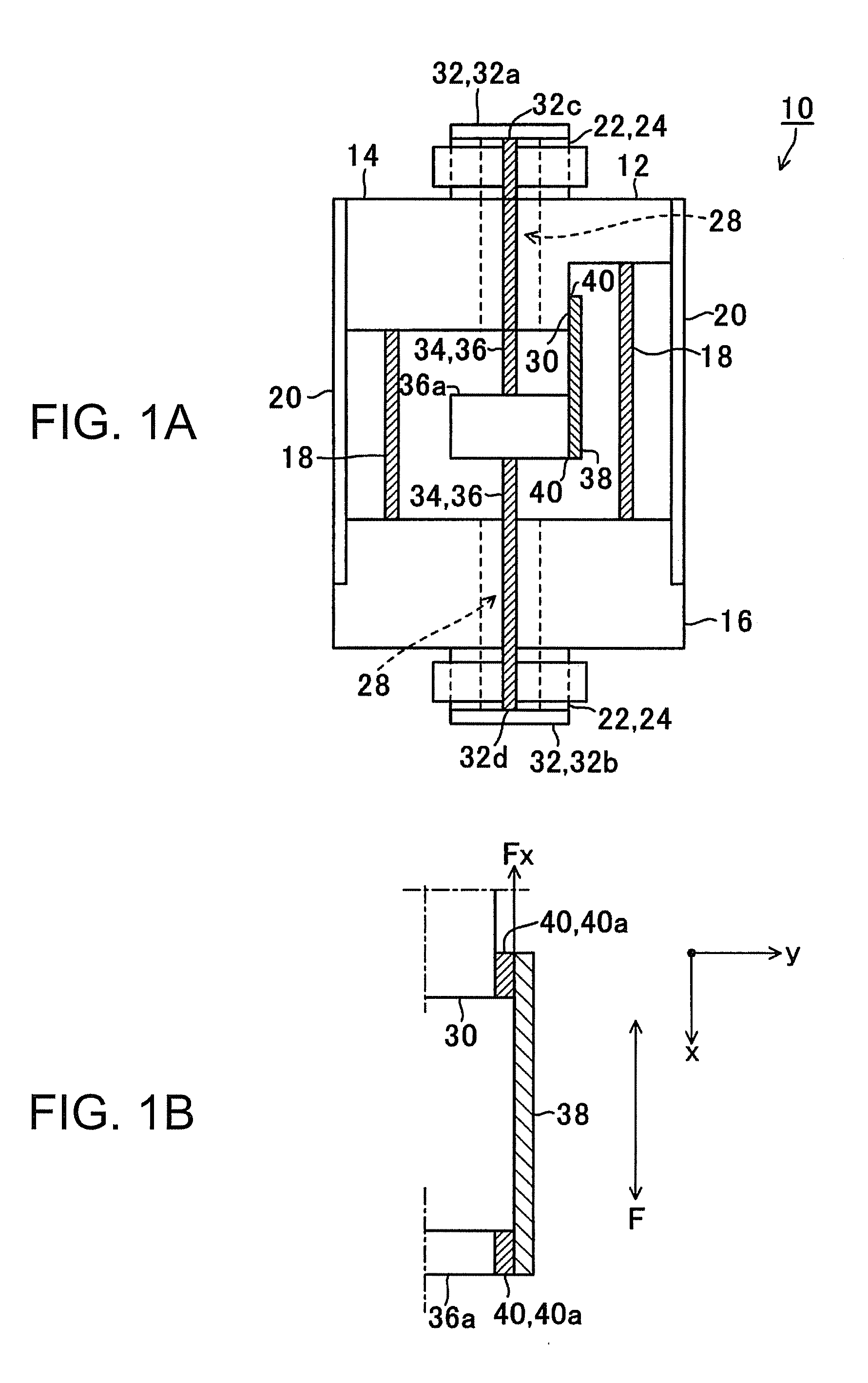
[0068]As described above, since the pressure sensor 10 of the first embodiment does not use oil as a structural component, a problem of leakage of the oil does not occur. Since the force transmitting unit 34 applies its force to the pressure sensitive element 38 only from the direction of the end face of the pressure sensitive element 38, it is possible to improve the sensitivity of the pressure sensor 10.
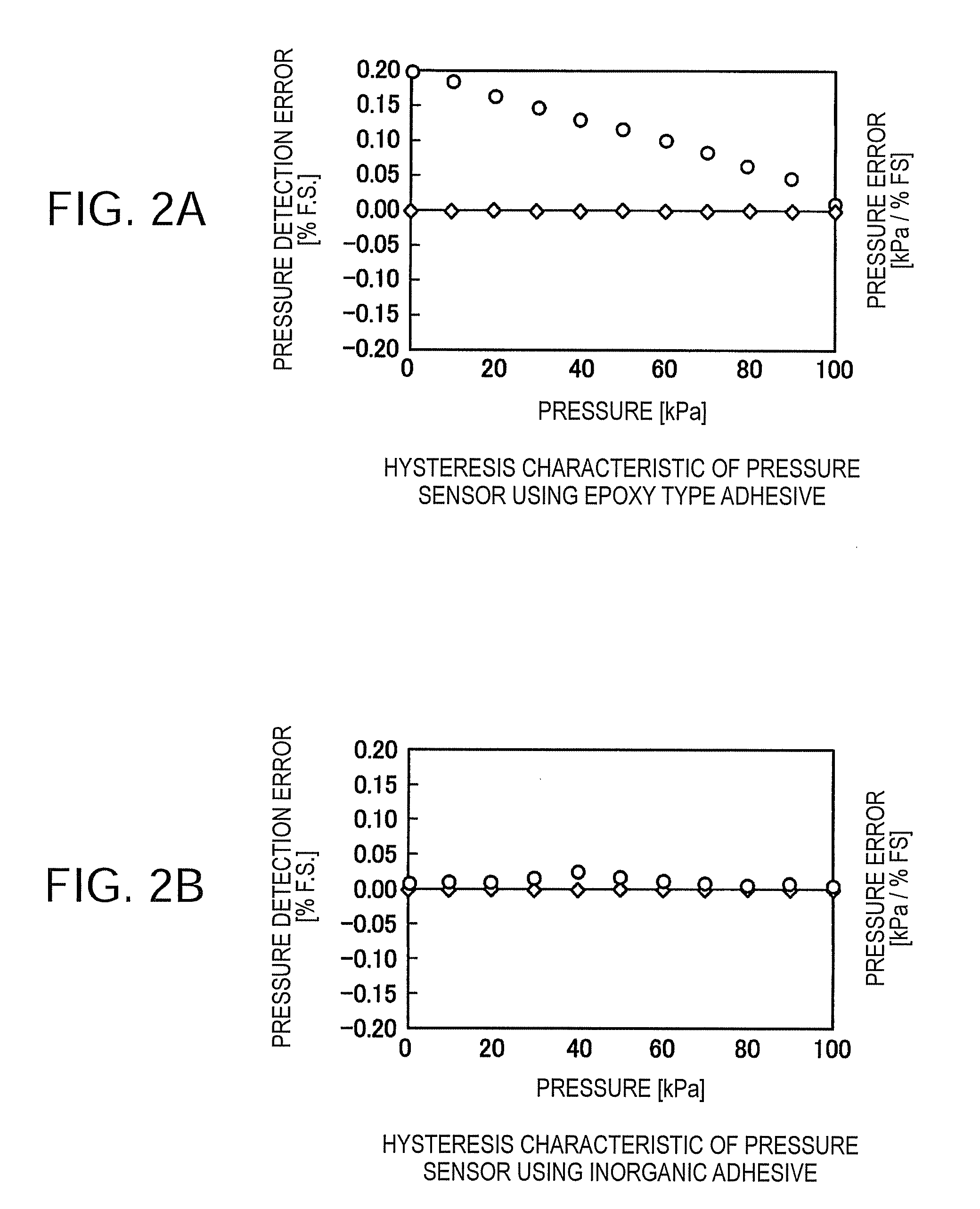
[0069]However, while the sensitivity of the pressure sensor 10 was improved, an inherent problem as described later was highlighted. As shown in FIG. 1B, the pressure sensitive element 38 is supported such that both ends of the pressure sensitive element 38 are respectively connected to the movable member 36a and the fixing member 30 with respective adhesive layers 40a therebetween. In the early stage, the inventor of the present invention carried out testing of supporting and fixing of the pressure sensitive element 38 by using an epoxy type or silicon type resin adhesive which is...
third embodiment
[0085]In the third embodiment, in particular, the upper end face plate is made of the hermetic terminal plate 114 and a hermetic terminal 148 is inserted to pass through the hermetic terminal plate 114 so that a signal of the pressure sensitive element 138 can be taken out.
[0086]In addition to the above configuration, in the embodiment, the pressure sensitive element 138 constituted of the double-ended tuning fork resonator is so configured that an attachment base portion at one end side is fixed to the movable member 137 and an attachment base portion at the other end side is fixed to the boss part 139 of the hermetic terminal plate 114. An inorganic adhesive including aluminum oxide and a Si compound is used for fixing the pressure sensitive element 138, and an adhering layer 150 is disposed between the base portion of the pressure sensitive element 138 and a face to be bonded. The movable member 137 is repeatedly brought close to or separated from the boss part 139 by detection o...
fourth embodiment
[0094]Also, in the fourth embodiment, an inorganic adhesive including aluminum oxide and a Si compound is used in order to fix the pressure sensitive element 238. Adhesive layers 250 are respectively interposed between tip portions at respective both end bases of the pressure sensitive element 238 in the detection axis direction and bonding targeted faces. With this configuration, even when the pressure sensitive element 238 receives a compressive or tensile force by an operation for pressure inspection, the compressive or tensile force is applied to the adhesive layers 250 in a direction of thickness of the adhesive layers. However, since each of the adhesive layers 250 is formed to be rigid by the inorganic adhesive, the compressive or tensile force is not absorbed nor alleviated by the adhesive layers 250 and is surely transmitted to the pressure sensitive element 238 through each adhesive layer as a rigid coupling layer. As a result, an error in the pressure detection can be eli...
PUM
| Property | Measurement | Unit |
|---|---|---|
| pressure | aaaaa | aaaaa |
| pressures | aaaaa | aaaaa |
| pressure | aaaaa | aaaaa |
Abstract
Description
Claims
Application Information