Differential scanning calorimeter

a scanning calorimeter and scanning calorimeter technology, applied in the field of differential scanning calorimeters, can solve the problems of inability to precisely detect the amount of heat that the sample emits or absorbs in spare compared with that of the reference sample on the basis of the difference between both temperatures, and the inability to precisely detect the amount of heat that the sample emits or absorbs in spare compared with that of the reference sample, so as to improve the heat conductivity of the heat resistan

Inactive Publication Date: 2010-09-28
HITACHI HIGH TECH SCI CORP
View PDF17 Cites 12 Cited by
  • Summary
  • Abstract
  • Description
  • Claims
  • Application Information

AI Technical Summary

Benefits of technology

[0009]An advantage of some aspects of the invention is to provide a differential scanning calorimeter that can detect exactly the calorie variation of the measured sample on the basis of the temperature difference between the sample container and the reference container without being influenced with the irregularity of heat incoming from the surrounding and the noise components.
[0016]According to this configuration, the weight of each container and each sample contained in each container and the load to the heat-resistance member caused by the thermal expansion or thermal contraction corresponding to the temperature variation does not cause a warp but axis force because the heat-resistance member is arranged along the vertical direction. Hence, the sectional dimension of the heat-resistance member can be made minimum. The surface of each container to load the sample is approximately vertical to the direction where the heat-resistance member is arranged. Therefore, without considering the interference of the container and the heating furnace with the heat inflow part, the protruding length from both sides of the heat inflow part of the heat-resistance member can be suppressed to the minimum. The response time constant can be made short by raising the heat conductivity of the heat-resistance member, since the sectional dimension and the length of the heat-resistance member are in the minimum respectively.
[0017]According to the above-mentioned differential scanning calorimeter, the temperature difference between the sample container and the reference container can be detected exactly by installing the heat-resistance member without being influenced with the irregularity of heat coming from the surroundings and the noise components. As result, the calorie variation of the measured sample can be measured exactly on the basis of the temperature difference between the sample container and the reference container.

Problems solved by technology

However, if the contact condition between the transmitting plates to install the sample container and the reference container and the ring-shaped lower support plate to transmit heat to the heat transmitting plate is not uniform in the known differential scanning calorimeter, as disclosed in JP-A-2000-28559, the heat amount of the sample container coming from the heat transmitting plate is not the same as that of the reference container.
Therefore, the known apparatus has disadvantage that the amount of heat which the sample emits or absorbs in spare compared with that of the reference sample on the basis of the difference of both temperatures can not be detected exactly.
If the noise components are transmitted to the sample container and the reference container via the heating furnace, the heat buffer plate, the lower support plate and the heat transmitting plate from the heater, then the detected temperature difference may contain noise components due to the noise components of the incoming heat.
Hence, the known apparatus has a problem that the amount of heat that the sample emits or absorbs in spare compared with that of the reference sample cannot be detected exactly.

Method used


Image

  • Differential scanning calorimeter
  • Differential scanning calorimeter
  • Differential scanning calorimeter

Examples


second embodiment

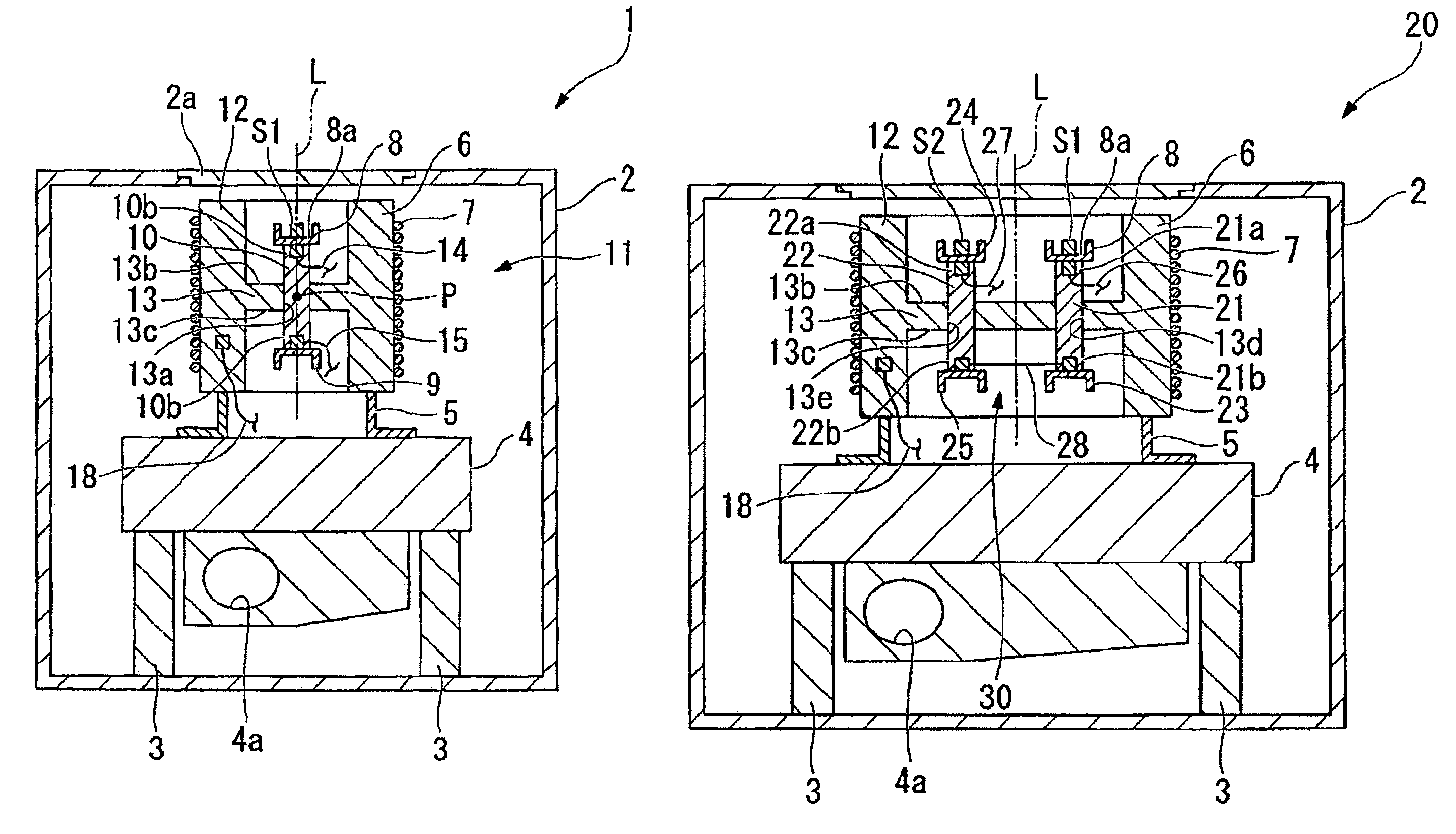
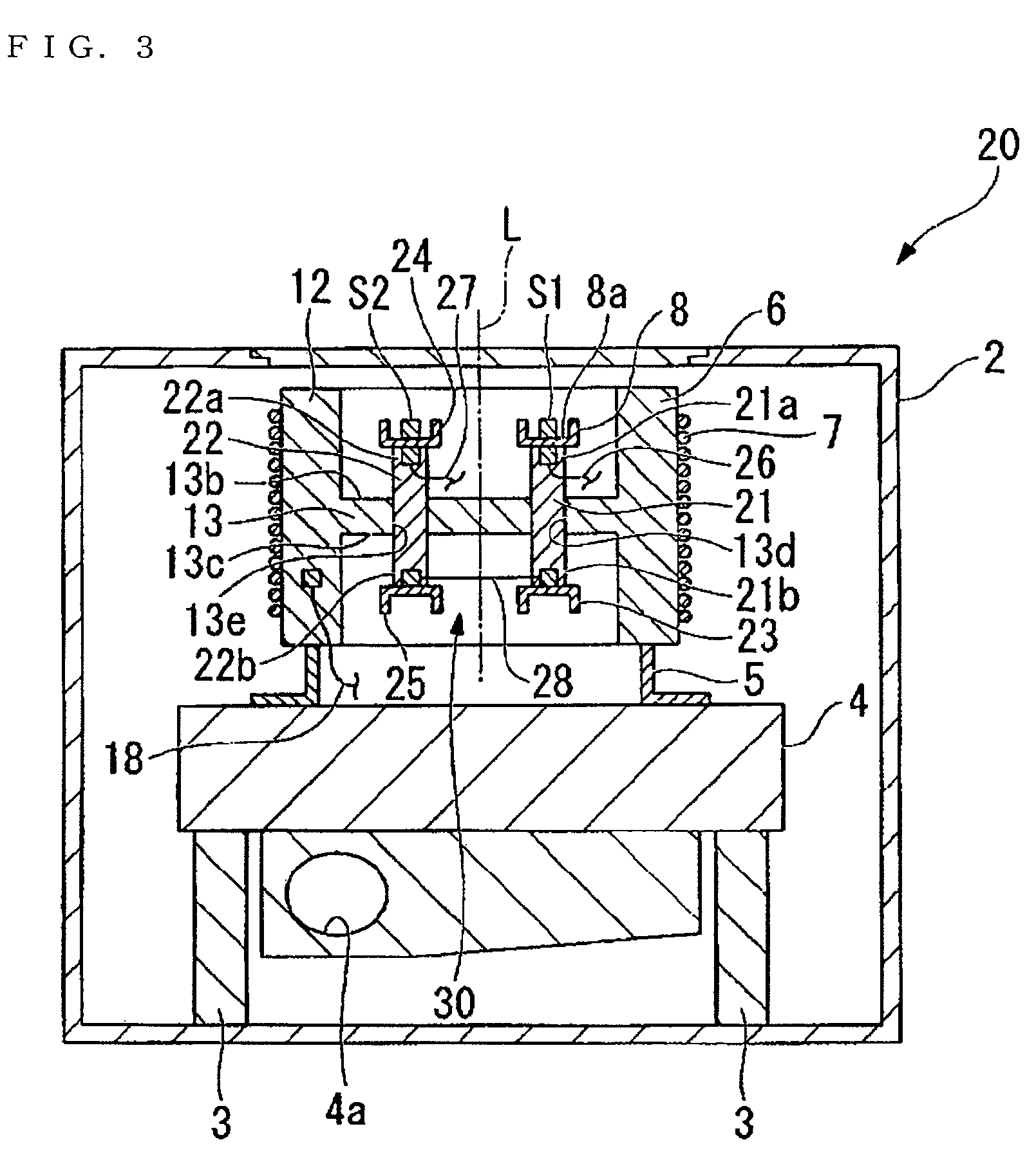
[0036]FIGS. 3 and 4 show a second embodiment of the invention. In the second embodiment of the invention, the same elements as those of the first embodiment are denoted by the same numerals and explanation thereof will be omitted.

[0037]In a differential scanning calorimeter 20 according to the second embodiment of the invention, a pair of through-holes 13d and 13e are formed at the heat inflow part 13 of the heat sink 6, and the first heat-resistance member 21 and the second heat-resistance member 22 are secured at the heat inflow part 13 penetrating the corresponding through-holes 13d and 13e, respectively. The first heat-resistance member 21 and the second heat-resistance member 22 have an approximately bar shape with a uniform section, and may be made of a material which has heat conductivity lower than that of the material of the heat sink 6. For example, the heat-resistance members 21 and 22 may be made of constantan. The first heat-resistance member 21 and the second heat-resi...


PUM

PropertyMeasurementUnit
differential scanning calorimeteraaaaaaaaaa
outer circumferenceaaaaaaaaaa
heat-resistanceaaaaaaaaaa

Abstract

There is provided a differential scanning calorimeter for exactly measuring a calorie variation of the measured sample on the basis of the temperature difference between sample container and the reference container without the influence of the heat irregularity incoming from the surroundings and the noise components. The differential scanning calorimeter includes a heating furnace of an approximately H-shaped section having an approximately drum-shaped wall part and an approximately plate-shaped heat inflow part, a heater disposed outside the wall part so as to heat the heating furnace, a approximately bar-shaped heat-resistance member that is arranged along the center axis L of the wall part, that protrudes from both sides of the heat inflow part by an approximately equal length, that is made of a material heat conductivity lower than that of the material of the heating furnace, a sample container disposed at one end of the heat-resistance member, a reference container disposed at the other end of the heat-resistance member, and a differential heat flow detector measuring a difference between the temperature of the sample container and the temperature of the reference container as a measured value.

Description

RELATED APPLICATIONS[0001]This application claims priority under 35 U.S.C. §119 to Japanese Patent Application No. JP2006-343935 filed Dec. 21, 2006, the entire content of which is hereby incorporated by reference.BACKGROUND OF THE INVENTION[0002]1. Field of the Invention[0003]The present invention relates to a heat analysis apparatus for measuring the variation of the property of a sample according to the temperature variation. In Particular, the invention relates to a differential scanning calorimeter for measuring the amount of heat that a sample emits or absorbs in spare, compared with that of the reference sample on the basis of the temperature difference (differential heat) between the sample and a reference sample when the temperature of both of the samples varies.[0004]2. Description of the Related Art[0005]A differential scanning calorimeter is an apparatus for detecting differentially the amount of heat that a sample emits or absorbs in spare compared with a reference samp...

Claims


Application Information

Patent Timeline
Patent Type & Authority Patents(United States)
IPC IPC(8): G01K17/08G01N25/20
CPCG01N25/20
Inventor TERAMOTO, YOSHIHIKO
Owner HITACHI HIGH TECH SCI CORP
Why Eureka
Try Eureka