Inner conductor end contacting coaxial connector and inner conductor adapter kit

a coaxial connector and inner conductor technology, applied in the direction of coupling contact members, coupling devices, coupling devices, etc., can solve the problems of inconvenient connector manufacturing and installation, unacceptable increase in connector cost,

Inactive Publication Date: 2010-09-28
COMMSCOPE TECH LLC
View PDF21 Cites 26 Cited by
  • Summary
  • Abstract
  • Description
  • Claims
  • Application Information

AI Technical Summary

Benefits of technology

[0049]As shown for example in FIGS. 23 and 24, non-uniform leading edge 35 contacting functionality may also be added proximate the contact surface 33 of the adapter 17 via a contact surface spring contact 42, such as a circular coil spring 21. Alternatively, as shown for example in FIG. 23, the contact surface spring contact 42 may be applied as a variation of the ring 38 with spring fingers, here extending radially inward as shown in FIGS. 26 and 27, seated proximate the contact surface 33. Also in the present embodiment(s), an engagement surface 43 of either a plug end or outward biased spring finger(s) 41 of the adapter 17 is demonstrated extended longitudinally, as best shown in FIGS. 24 and 25, to enable the adapter 17 to couple with an extended length of the inner diameter of the hollow inner conductor 27 provided with a helical corrugation 54. Thereby, a circumferential contact against at least one half of a helical corrugation 45 loop around the inner diameter of the hollow inner conductor 27 may be obtained.
[0051]One skilled in the art will appreciate several potential benefits of easily configurable and exchangeable inner contact 3 arrangements. By providing a range of available inner contact 3 arrangements, the number of unique coaxial cable 1 configurations that may be required to satisfy existing coaxial cable 37 dimensions and / or end preparations may be significantly reduced. The longitudinal biased leading edge 35 coupling provided by these configurations may provide improved electrical coupling between the inner contact 3 and the inner conductor 27 that may be resistant to degradation due to vibration and / or thermal expansion cycling of coaxial cable 37 and / or the installed coaxial connector 1, without the expense of an inner conductor bellows. By enabling compatibility with both flush cut and protruding inner conductor 27 cable end configurations, the exchangeable inner contact 3 arrangements may allow the user to install the coaxial connector 3 with whichever cable end preparation tool the user may have available at the time of installation.
[0052]The inner contact 3 arrangement(s) may be easily integrated with existing coaxial connector 1 configurations with a minimum of engineering rework and / or tooling modification. Depending, for example, upon the desired operating frequencies, the required modifications may be limited to the exchange of a conventional inner contact configuration with an inner contact 3 arrangement as described herein, enabling the replacement of multiple existing cable specific coaxial connector 1 models with a single coaxial connector 1 model.

Problems solved by technology

To prepare these end configurations, an end user may also be required to purchase and maintain a range of different cable / connector combination specific cable end saw guides and insulation coring / striping tools at significant additional expense.
The inner conductor bellows element and numerous individual threaded or otherwise precision machined elements of the inner contact and inner contact assembly may unacceptably increase the connector cost and / or complicate connector manufacture and installation.

Method used


Image

  • Inner conductor end contacting coaxial connector and inner conductor adapter kit
  • Inner conductor end contacting coaxial connector and inner conductor adapter kit
  • Inner conductor end contacting coaxial connector and inner conductor adapter kit

Examples


Embodiment Construction

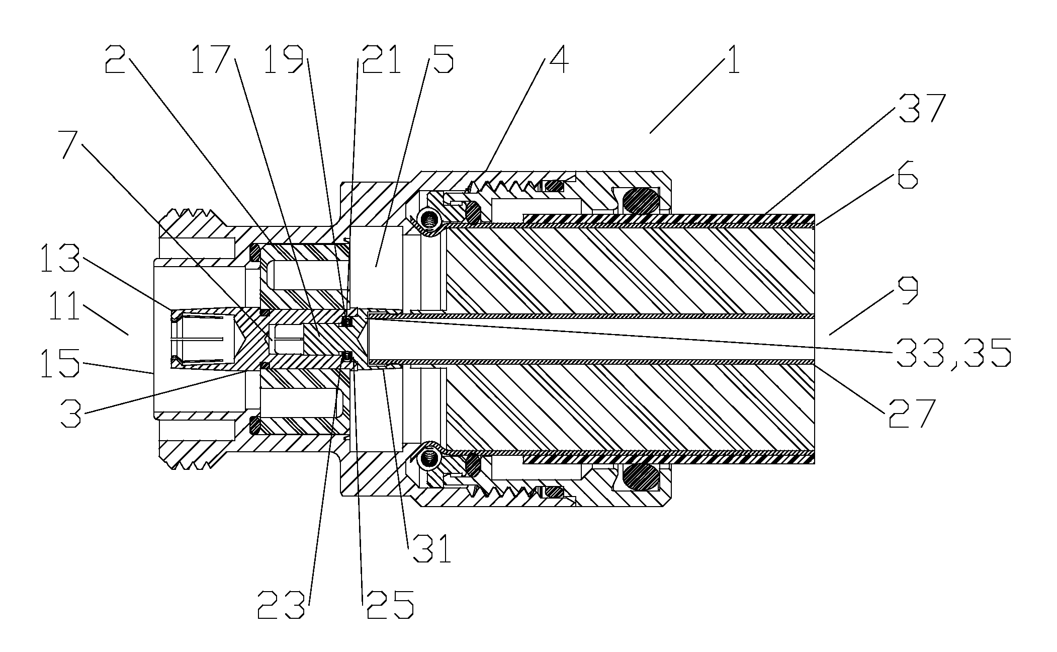
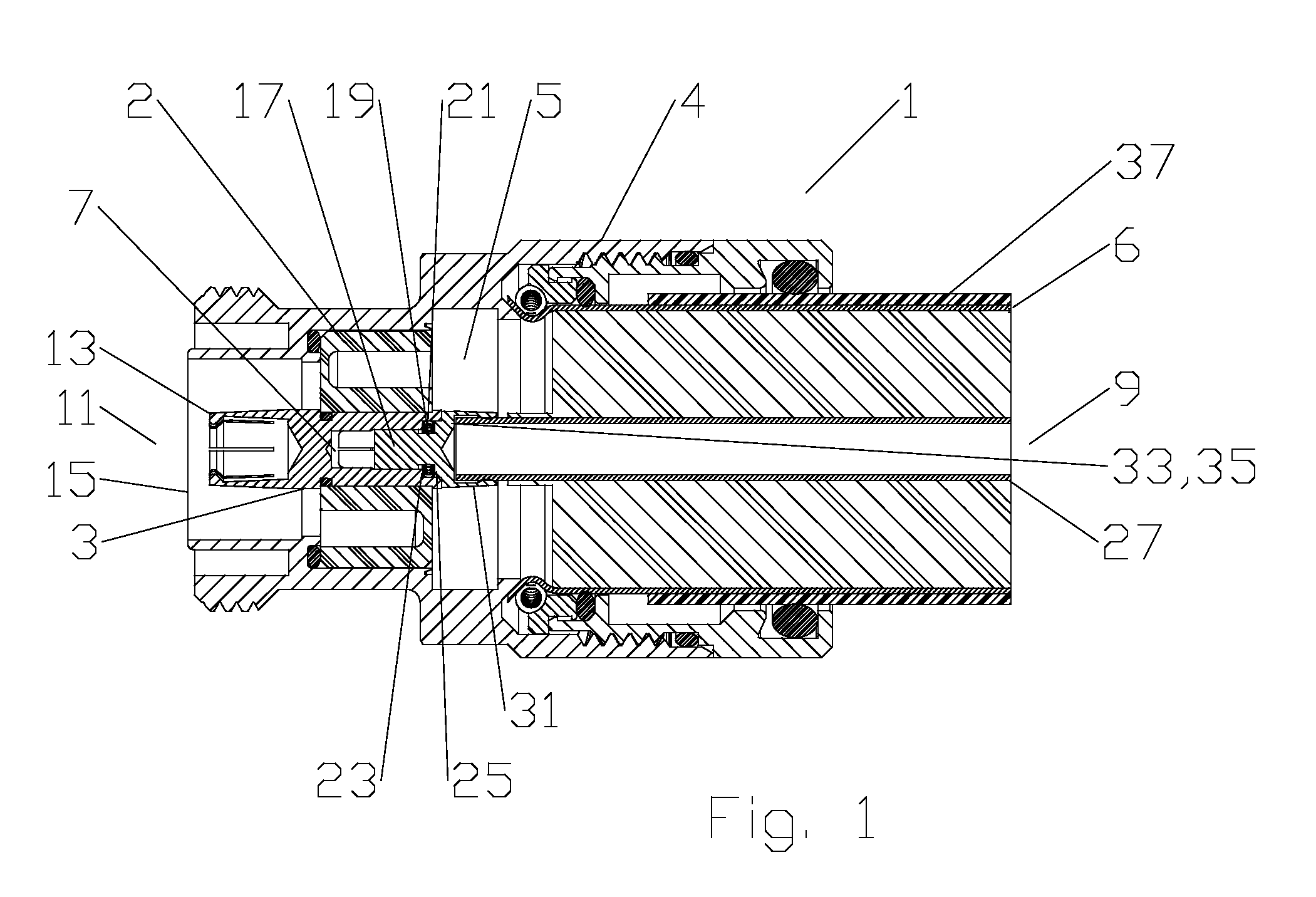
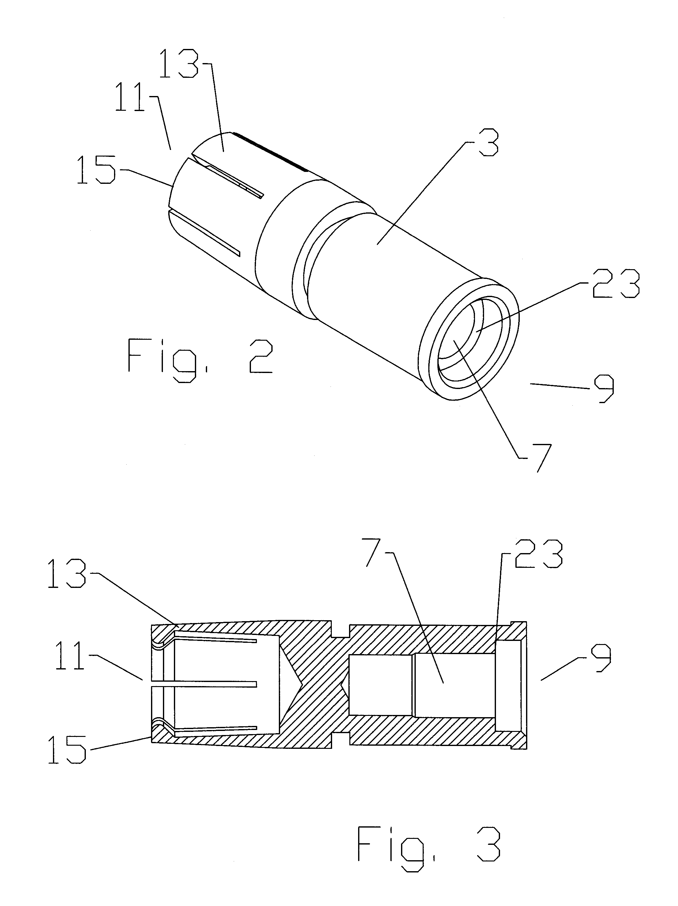
[0040]As shown in FIG. 1, a first embodiment of a coaxial cable connector 1 has an inner contact 3 supported by an insulator 2 coaxial within a connector body 4 with a connector body bore 5. The outer conductor 6 is demonstrated coupled with the connector body 4 by leading edge clamping. One skilled in the art will appreciate that the outer conductor 6 to connector body 4 coupling may be alternatively configured according to any desired coupling arrangement, such as interference fit, crimp connection, threading and / or wedge action retention. Best shown in FIGS. 2 and 3, the inner contact 3 has an adapter bore 7 open to a cable end 9 of the inner contact 3. The connector end 11 of the inner contact 3 may be formed for example as a pin or interface spring basket 13 dimensioned according to the selected connector interface 15. The connector interface 15 may be any desired standardized or proprietary connector interface.

[0041]One skilled in the art will appreciate that the cable end 9 a...


PUM


Abstract

A coaxial connector is provided with a connector body dimensioned to couple with the outer conductor, an insulator supporting an inner contact coaxial within a bore of the connector body. A spring contact may be positioned to contact an end of the inner conductor. Alternatively, an adapter may be mountable in an adapter bore of the inner contact, the adapter bore open to a cable end of the inner contact. The spring contact mountable within the adapter bore, the spring contact biasing the adapter against an end of the inner conductor.

Description

BACKGROUND OF THE INVENTION[0001]1. Field of the Invention[0002]The invention relates to inner contacts for coaxial cable connectors. More particularly the invention relates to a coaxial connector with an inner contact assembly with a resilient inner conductor end contact configuration that may be reconfigurable for installation upon multiple coaxial cable configurations and / or cable end preparations.[0003]2. Description of Related Art[0004]Coaxial cables of standardized diameter and RF power handling capability may each feature inner conductors of different configurations and / or materials. For example, the inner conductor may be aluminum, copper, copper clad aluminum, and may be solid, hollow, corrugated and / or smooth walled. Further, the inner dimensions of hollow inner conductors may vary significantly, although the inner conductor outer diameter has been standardized.[0005]Coaxial connectors may each be designed for a specific coaxial cable, requiring a manufacturer to design, m...

Claims


Application Information

Patent Timeline
Patent Type & Authority Patents(United States)
IPC IPC(8): H01R9/05
CPCH01R13/15H01R24/564H01R9/0521H01R2103/00H01R24/566
Inventor ISLAM, NAHID
Owner COMMSCOPE TECH LLC
Why Eureka
Try Eureka