Navigated pin placement for orthopaedic procedures

a technology of orthopaedic procedures and needle placement, which is applied in the field of orthopaedic surgical procedures, can solve the problems of multiple degree of freedom, deterioration of bones, and affecting the ability of natural joints to function properly, so as to avoid the high cost and complexity of such systems, facilitate accurate bone cutting or resection, and ensure the accuracy of positioning of bone screws or pins

Inactive Publication Date: 2010-09-28
DEPUY PROD INC
View PDF18 Cites 47 Cited by
  • Summary
  • Abstract
  • Description
  • Claims
  • Application Information

AI Technical Summary

Benefits of technology

[0014]In another aspect of the invention, a guide apparatus is provided that facilitates accurate placement of a guide or support pin into a bone. In one embodiment, the guide apparatus comprises a mounting body that is fastened to the bone in the proximity of a pre-determined guide pin location. A guide arm supports a position adjustment assembly over the guide pin location. The position adjustment assembly permits gross and fine adjustments of a pin guide. In this preferred embodiment of the invention, the pin guide is provided with a position tracking element that works through a localizing device or sensor to interactively evaluate the spatial position of the pin guide relative to the pre-determined guide pin location. Once the pin guide has been manipulated into coincidence with the pre-determined position, the surgeon can use the guide to drive a support pin into the bone.
[0016]It is one object of the present invention to provide systems and methods to facilitate making accurate cuts or resections of bone at a surgical site. It is a further object of the invention to utilize known image guide surgical techniques, while avoiding the high cost and complexity of such systems.

Problems solved by technology

Damage or disease can deteriorate the bones, articular cartilage and ligaments of human joints, such as the knee, which can ultimately affect the ability of the natural joint to function properly.
These complex devices include multiple degree-of-freedom fine tuning adjustments that can be “dialed in” to optimize the orientation of the saw guide.
While accurate bone cuts can be made with these complex devices, they are naturally more expensive and require greater maintenance than cutting blocks as simple as or more simple than the assembly 10 of FIG. 1.
As the disclosure of the '664 patent reveals, the typical image guided surgery system is complex and requires a great deal of equipment to provide real-time simulation and graphic display of the surgical site.

Method used


Image

  • Navigated pin placement for orthopaedic procedures
  • Navigated pin placement for orthopaedic procedures
  • Navigated pin placement for orthopaedic procedures

Examples


Embodiment Construction

[0028]For the purposes of promoting an understanding of the principles of the invention, reference will now be made to the embodiments illustrated in the drawings and described in the following written specification. It is understood that no limitation to the scope of the invention is thereby intended. It is further understood that the present invention includes any alterations and modifications to the illustrated embodiments and includes further applications of the principles of the invention as would normally occur to one skilled in the art to which this invention pertains.

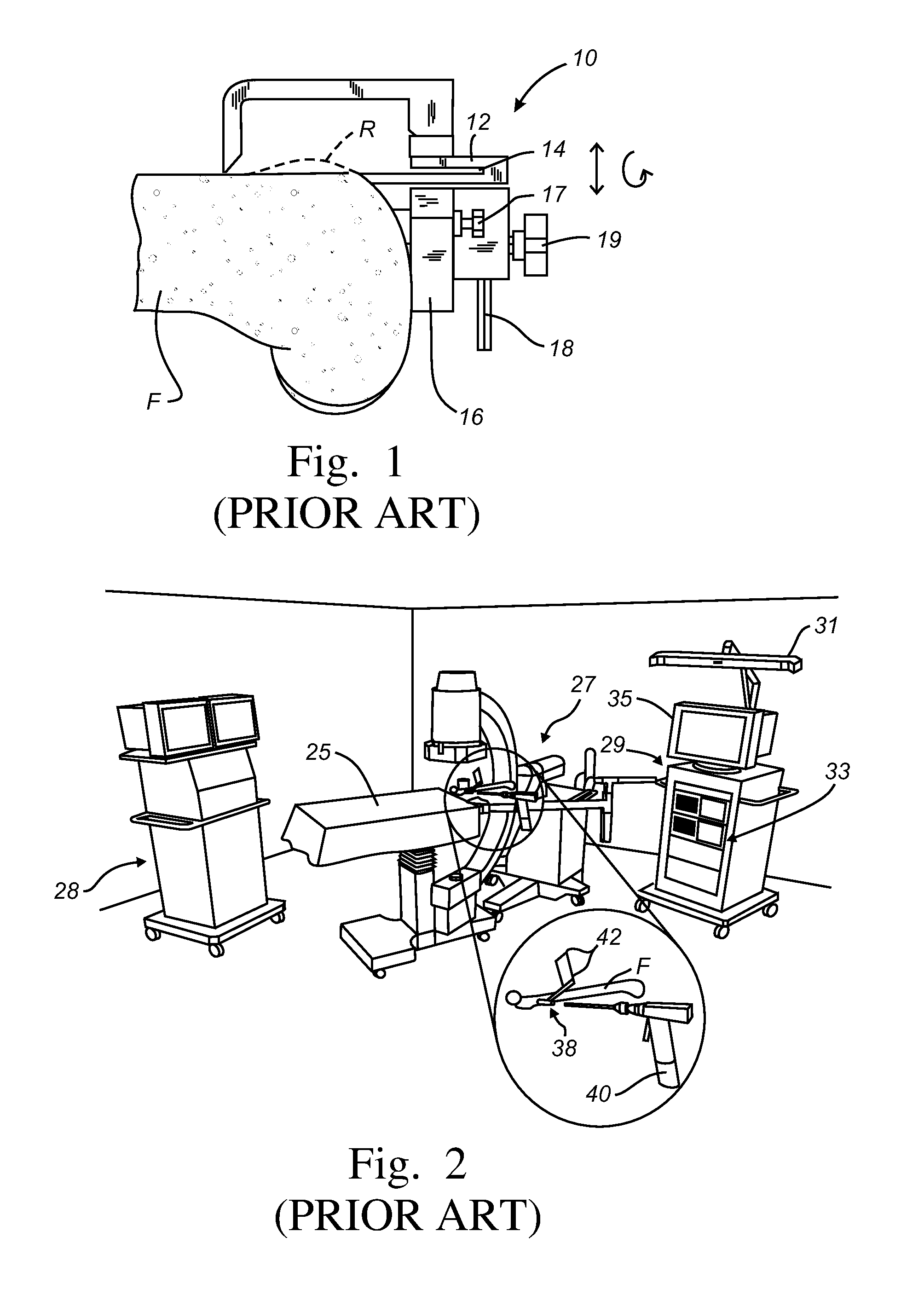
[0029]The present invention provides systems and methods that utilize image guided surgical techniques and systems. More particularly, the invention utilizes a localizing device, such as the localizing sensor 31 shown in FIG. 2, and position tracking elements, such as the element 42, that cooperate with the localizing device to establish the spatial position of a component. A processor, like the processor 33 in ...


PUM


Abstract

Systems and methods are provided for navigated placement of bone engaging elements, such as support pins used to support a cutting block on a bone for resection. In one embodiment, a guide apparatus is configured to be mounted to a bone and provides multi-degree of freedom gross and fine adjustments of a pin guide. The pin guide carries a position tracking element so that its real-time spatial position relative to a location on the bone can be evaluated.

Description

BACKGROUND OF THE INVENTION[0001]The present invention relates to systems and methods for accurate positioning of tools, fasteners and implants within a patient. More particularly, the invention relates to orthopaedic surgical procedures requiring accurate shaping of the bone or placement of bone engaging elements.[0002]Damage or disease can deteriorate the bones, articular cartilage and ligaments of human joints, such as the knee, which can ultimately affect the ability of the natural joint to function properly. To address these conditions, prosthetic joints have been developed that are mounted to prepared ends of the bones of the joint, namely the tibia and femur in the case of a knee prosthesis.[0003]The implant components define interior mounting surfaces that often require involved cuts into the bone, such as the distal end of the femur or the proximal end of the tibia. The implant components are selected to restore or emulate as much of the natural motion of the knee joint as ...

Claims


Application Information

Patent Timeline
Patent Type & Authority Patents(United States)
IPC IPC(8): A61B17/56A61B17/88A61B17/90A61F2/46A61B17/16A61B17/17A61B19/00
CPCA61B17/17A61B17/1703A61B17/1725A61B17/1633A61B19/50A61B34/10
Inventor HAYDEN, ADAM IREDELL
Owner DEPUY PROD INC
Why Eureka
Try Eureka