Photosensor circuits including a switch mode power converter

a photosensor circuit and power converter technology, applied in the direction of pulse generators, pulse techniques, relays, etc., can solve the problems of high heat generation, inconvenient use, and inefficient resistors, and achieve the effect of cost prohibitive in the implementation of switch mode power converters

Active Publication Date: 2010-09-28
TYCO ELECTRONICS LOGISTICS AG (CH)
View PDF4 Cites 57 Cited by
  • Summary
  • Abstract
  • Description
  • Claims
  • Application Information

AI Technical Summary

Problems solved by technology

However, these resistors are typically inefficient and generate high heat.
Also, the high heat generated by the resistors can lead to problems with reliability and longevity in the resistors and in other electronic components situated near the resistors.
The requirement for multiple transistors or a micro-controller may cause the implementation of switch mode power converters to be cost prohibitive in some applications, such as in photo controllers.
However, increasing the value also slows the time it takes for the current pulse of transistor Q3 to be turned off, increasing commutation losses in transistor Q3, and increases the time for the regulator circuit to stabilize at startup.
If the current shunted is too much, the base current of transistor Q3 will not be enough to turn transistor Q3 completely on.

Method used


Image

  • Photosensor circuits including a switch mode power converter
  • Photosensor circuits including a switch mode power converter
  • Photosensor circuits including a switch mode power converter

Examples


Embodiment Construction

[0035]The present invention now will be described more fully hereinafter with reference to the accompanying drawings, in which illustrative embodiments of the invention are shown. In the drawings, the relative sizes of regions or features may be exaggerated for clarity. This invention may, however, be embodied in many different forms and should not be construed as limited to the embodiments set forth herein; rather, these embodiments are provided so that this disclosure will be thorough and complete, and will fully convey the scope of the invention to those skilled in the art.

[0036]It will be understood that, although the terms first, second, etc. may be used herein to describe various elements, components, regions, layers and / or sections, these elements, components, regions, layers and / or sections should not be limited by these terms. These terms are only used to distinguish one element, component, region, layer or section from another region, layer or section. Thus, a first elemen...


PUM


Abstract

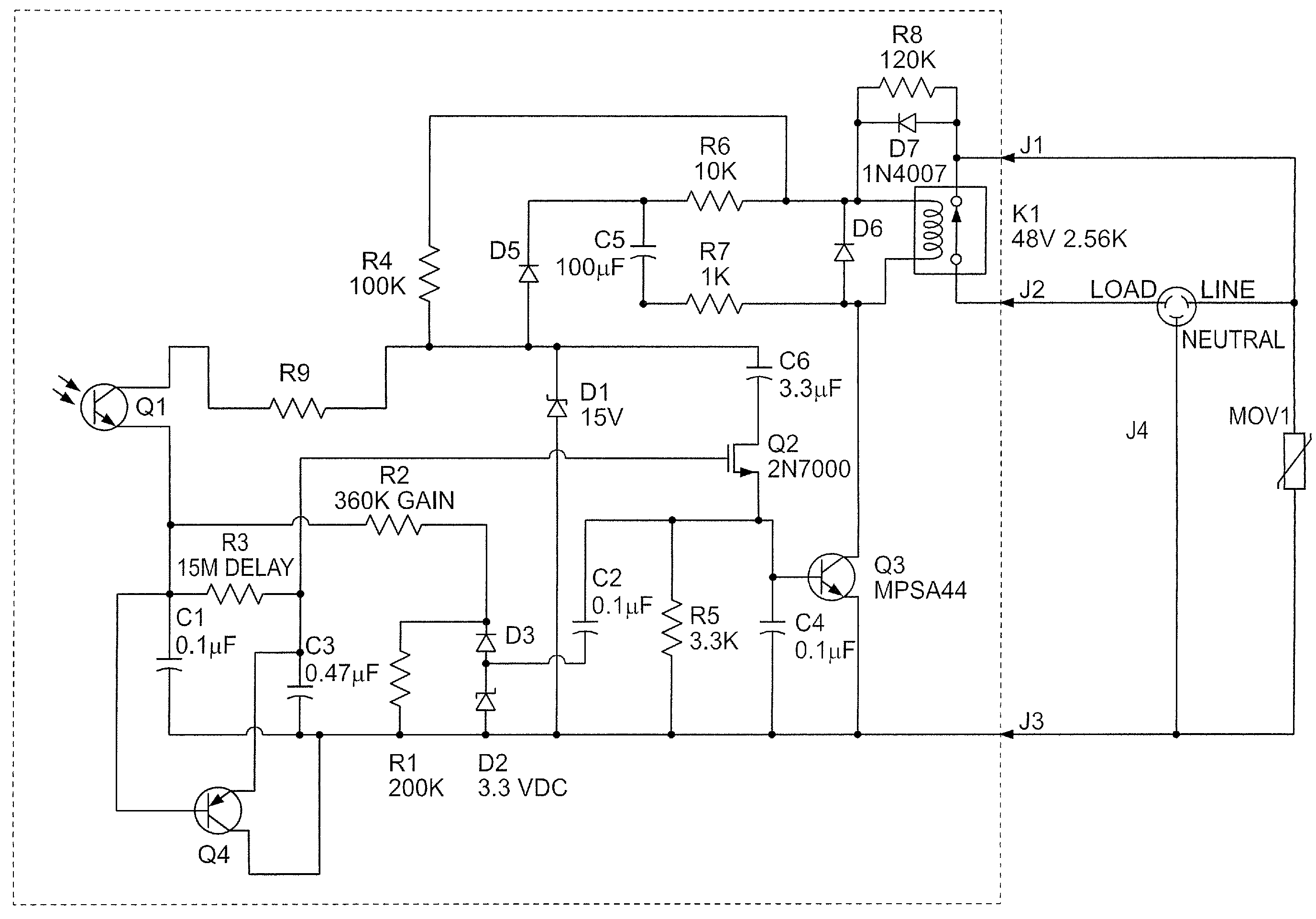
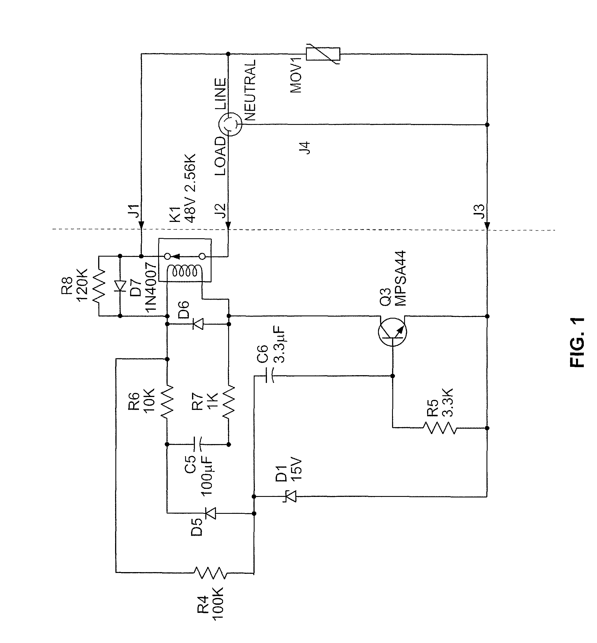
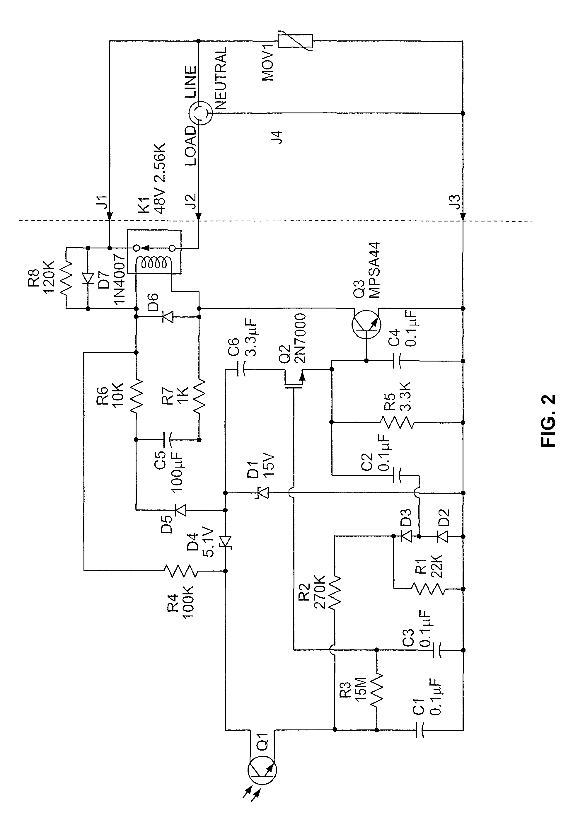
Photosensor circuits include a relay coil configured to control application of an alternating current (AC) power source to a load. A pulse width modulator circuit is configured to generate a pulse width modulated signal having a pulse width that varies responsive to an average voltage across the relay coil. A drive transistor controls the average voltage across the relay coil responsive to the pulse width modulated signal. A photo control circuit controls application of the pulse width modulated signal to the drive transistor responsive to a detected light level. A half-wave rectifier provide a power signal to the pulse width modulator circuit and the photo control circuit during one of the halves of the line cycle of the AC power source. The photo control circuit includes a phototransistor. A low pass filter circuit filters the output current of the phototransistor to provide a light level signal voltage. A select transistor couples the pulse width modulated signal to the drive transistor during one of the halves of the line cycle of the AC power source responsive to the light level signal voltage having a selected level. A capacitor coupled between the second terminal of the phototransistor and the neutral bus modulates an amount of positive feedback through the first terminal of the phototransistor proportional to a current flowing through the relay coil to provide hysteresis to control of the relay coil by the photosensor circuit.

Description

BACKGROUND OF THE INVENTION[0001]The present invention relates to photosensor circuits and, more particularly, photosensor circuits for light level switching control.[0002]Photo controllers are devices that automatically turn electrical devices on and off in response to the ambient light level. They are used, for example, on street lights to automatically turn them off during the day and on at night. They are also used on billboard lighting systems to turn the billboard lights on early at night, off late at night during periods of low vehicular traffic, on again during early morning rush hour periods when high traffic levels resume, and then off during the daylight hours. Photo controllers may also be used in reverse, for example, to turn a golf course water fountain on during the day and off at night.[0003]A variety of devices, including photo controllers may make use of power converters to convert relatively high voltage alternating current to relatively low voltage direct current...

Claims


Application Information

Patent Timeline
Patent Type & Authority Patents(United States)
IPC IPC(8): H01H35/14
CPCH05B37/0218Y02B20/46H05B47/11Y02B20/40
Inventor FLAHERTY, RICHARD CHARLES
Owner TYCO ELECTRONICS LOGISTICS AG (CH)
Why Eureka
Try Eureka