Ring-laser gyroscope system using dispersive element(s)

Inactive Publication Date: 2010-09-28
NASA
View PDF44 Cites 7 Cited by
  • Summary
  • Abstract
  • Description
  • Claims
  • Application Information

AI Technical Summary

Benefits of technology

[0008]Accordingly, it is an object of the present invention to provide a method and system for

Problems solved by technology

Unfortunately, conventional ring-laser gyroscopes suffer from a dead-band in their response as a result of backscattering as the ring-laser gyroscope rotates.
Light at the backscattered frequencies reduces the gyroscope's sensitivity to low rates of rotation.
However, a dithering mirror is a moving and noisy optical component while introduction of the Faraday

Method used


Image

  • Ring-laser gyroscope system using dispersive element(s)
  • Ring-laser gyroscope system using dispersive element(s)
  • Ring-laser gyroscope system using dispersive element(s)

Examples


Embodiment Construction

)

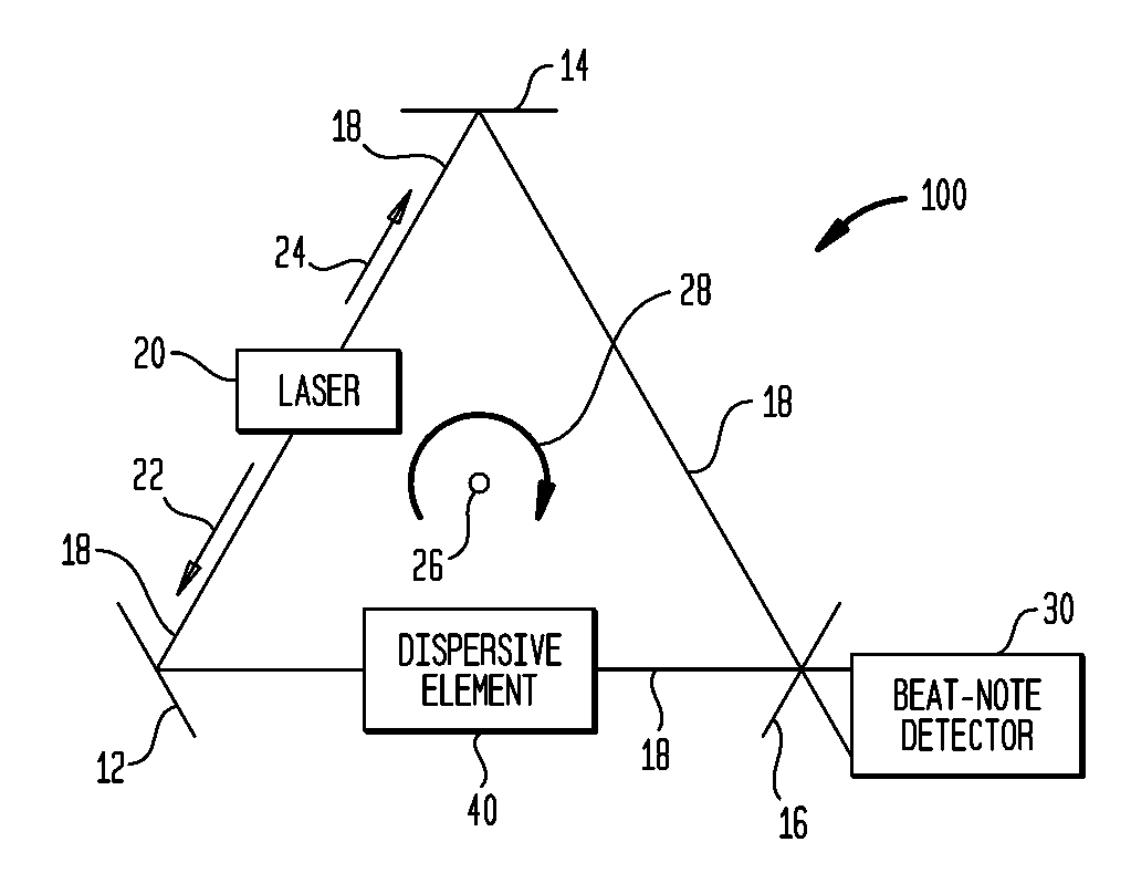
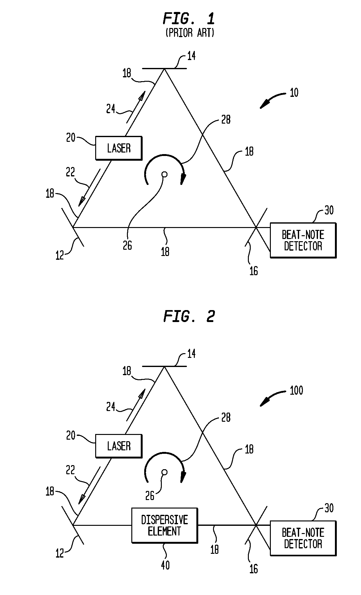
[0017]Referring again to the drawings and more particularly to FIG. 2, a ring-laser gyroscope system in accordance with an embodiment of the present invention is shown and is referenced generally by numeral 100. Elements of system 100 that are the same as those used in ring-laser gyroscope 10 (FIG. 1) use the same reference numerals and will not be discussed further herein.

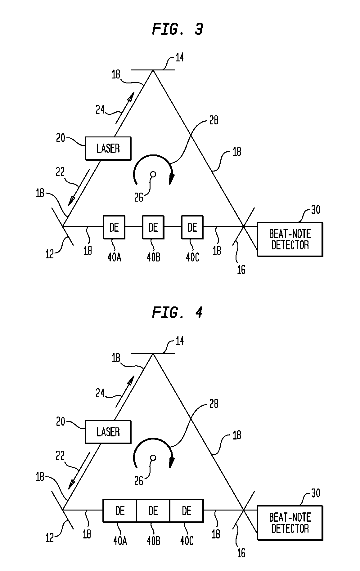
[0018]In general, the ring-laser gyroscope of the present invention includes at least one dispersive element that is optically coupled to the ring-laser gyroscope's optical path. For example, system 100 incorporates a dispersive element 40 along and in optical path 18 such that the light traversing optical path 18 passes through dispersive element 40. Dispersive element 40 performs two simultaneous functions. First, for a given rotation rate, dispersive element 40 increases the frequency difference (i.e., beat frequency) between the counter-propagating laser beams 22 and 24 as gyroscope system 100 rotates (e.g., ...


PUM


Abstract

A ring-laser gyroscope system includes a ring-laser gyroscope (RLG) and at least one dispersive element optically coupled to the RLG's ring-shaped optical path. Each dispersive element has a resonant frequency that is approximately equal to the RLG's lasing frequency. A group index of refraction defined collectively by the dispersive element(s) has (i) a real portion that is greater than zero and less than one, and (ii) an imaginary portion that is less than zero.

Description

CROSS-REFERENCES TO RELATED APPLICATIONS[0001]This application claims the benefit of U.S. Provisional Application No. 60 / 914,947, filed on Apr. 30, 2007.ORIGIN OF THE INVENTION[0002]The invention was made by an employee of the United States Government and may be manufactured and used by or for the Government for governmental purposes without the payment of any royalties.BACKGROUND OF THE INVENTION[0003]1. Field of the Invention[0004]This invention relates to ring-laser gyroscopes. More specifically, the invention is a ring-laser gyroscope system that incorporates one or more dispersive elements to improve sensitivity while suppressing the dead-band.[0005]2. Description of the Related Art[0006]Ring-laser gyroscopes are well known devices used in a variety of navigation, alignment, measurement and / or surveying systems. The operating principles of a ring-laser gyroscope will be explained briefly with the aid of FIG. 1 where an embodiment of a ring-laser gyroscope is illustrated and ref...

Claims


Application Information

Patent Timeline
IPC IPC(8): G01C19/64H01S3/083
CPCG01C19/66H01S3/083
Inventor SMITH, DAVID D.
Owner NASA
Why Eureka
Try Eureka