History-independent noise-immune modulated transformer-coupled gate control signaling method and apparatus

a transformer-coupled gate control and signaling method technology, which is applied in the direction of process and machine control, instrumentation, pulse technique, etc., can solve the problems of consuming power, reference clock signal generation, and consuming power, so as to improve noise immunity and reduce power consumption

Inactive Publication Date: 2010-09-28
CIRRUS LOGIC INC
View PDF178 Cites 8 Cited by
  • Summary
  • Abstract
  • Description
  • Claims
  • Application Information

AI Technical Summary

Benefits of technology

[0009]The above stated objective of providing a transformer-isolated gate drive circuit that requires few or no passive components to achieve a wide pulse width range with disable capability, provides robust and noise-immune operation without requiring a synchronization clock, is achieved in a gate drive control circuit and method of operation. The circuit may be provided by a transformer and a set of integrated circuits, one of which provides the control signal on the primary side of the transformer, and the other of which provides the gate drive signal from the secondary side of the transformer.
[0011]Blanking of the demodulator control can be provided after turn-on and / or turn-off events to improve noise immunity during switching events and to reduce power consumption. The blanking may be performed by stopping generation of the modulated control signal, ignoring the modulated control signal at the demodulator, or by encoding a blanking event according to a blanking code embedded in the modulated control signal.

Problems solved by technology

However, such implementations typically require a relatively large number of passive components to complete the circuit, such as resistors, capacitors and / or snubbing / protection diodes to ensure that the gate of the transistor that is coupled to the transformer secondary winding is not damaged or improperly controlled, and that the transformer does not saturate due to a net DC magnetization current from duty cycles other than 50%.
Solutions to the above, such as those disclosed in U.S. Pat. No. 5,206,540, either require driving multiple voltages to signal the isolated switching circuit to change the state of the power device gate control signal(s), or are subject to edge noise (spikes) that can mis-trigger the gate control signals.
Synchronization is generally required, by constructing or supplying a reference clock signal to the isolated switching circuit, and such reference clock signal generation consumes power and requires additional circuitry.

Method used


Image

  • History-independent noise-immune modulated transformer-coupled gate control signaling method and apparatus
  • History-independent noise-immune modulated transformer-coupled gate control signaling method and apparatus
  • History-independent noise-immune modulated transformer-coupled gate control signaling method and apparatus

Examples


Embodiment Construction

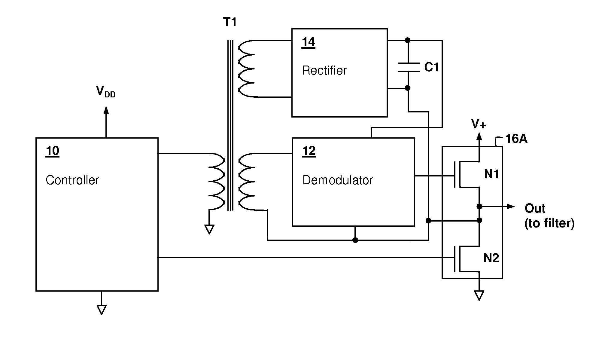
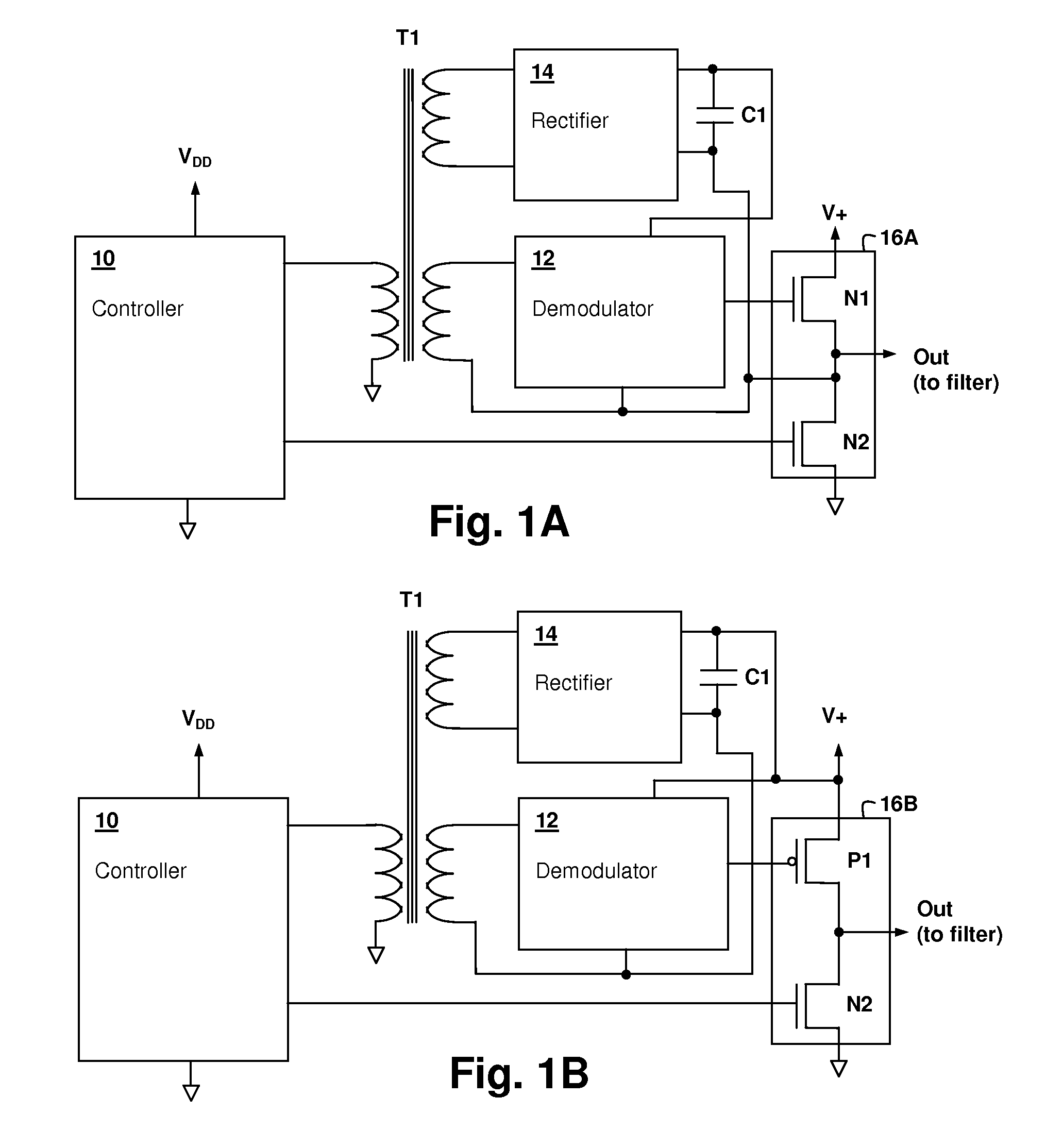
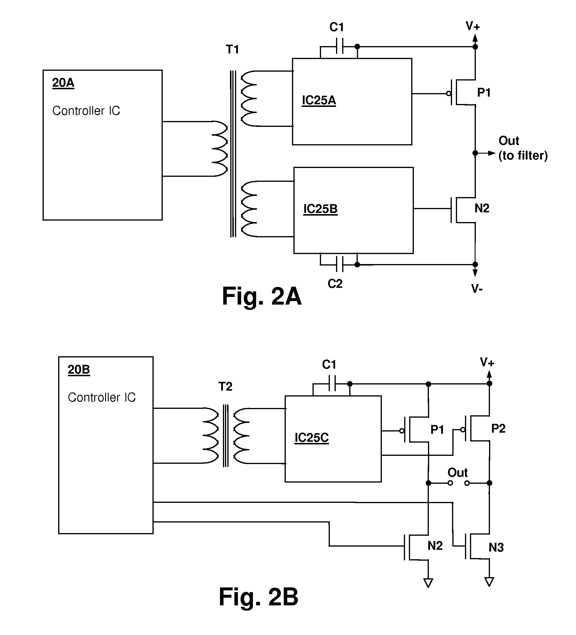
[0020]The present invention encompasses circuits and methods for providing drive signal(s) that control the gate(s) of one or more switching devices of a switching power stage. A transformer is used to isolate at least one gate drive circuit from a controller integrated circuit, and the control signal is modulated at a rate substantially higher than the switching control rate of the switching power stage, e.g., by a factor of 10, which permits transmission of additional or redundant information and robust operation with few additional components. The above-incorporated Parent U.S. patent application Ser. No. 11 / 954,202, discloses and claims such modulated control schemes and circuits. However, the present invention provides further robustness and noise-immunity by introducing specific modulation schemes that uses codes indicated by relative timings of transitions of the modulated control signal, to effect control of the switching circuits. Blanking of the modulated control signal or...


PUM


Abstract

A history-independent and noise-immune modulated transformer-coupled gate control signaling method and apparatus provides robust design characteristics in switching power circuits having a transformer-coupled gate drive. A modulated control signal at a rate substantially higher than the switching circuit gate control rate is provided from the controller circuit to a demodulator via transformer coupling. Codes specified by relative timing of transitions in multiple periods of the modulated control are assigned to gate-on and gate-off timing events that control the switching transistor gate(s) and unassigned patterns are decoded as gate-off events, reducing the possibility that a switching transistor will be erroneously activated due to noise. The modulated signal is constructed so that signal history is not required for decoding, eliminating any requirement of a reference clock. Blanking may be employed to conserve power between codes and to avoid mis-triggering due to noise events during power switching.

Description

[0001]This Application is a Continuation-in-Part of U.S. patent application Ser. No. 11 / 954,202, filed on Dec. 11, 2007, now U.S. Pat No. 7,656,687 having at least one common inventor and assigned to the same Assignee, the disclosure of which is incorporated herein by reference.BACKGROUND OF THE INVENTION[0002]1. Field of the Invention[0003]The present invention relates generally to power switching circuits having a transformer-coupled gate control, and more specifically, to a gate drive control circuit using a control signal modulated to a rate higher than the switching rate that encodes code sequence that indicate at least one switching time of the power switching circuits.[0004]2. Background of the Invention[0005]Transformer coupling of gate drive control is used in power switching circuits in which the transformer gate control signal either requires complete DC isolation from the switching control circuit, or in which the gate control voltage for at least one of the switching tr...

Claims


Application Information

Patent Timeline
Patent Type & Authority Patents(United States)
IPC IPC(8): H02M3/335H02M5/40
CPCH03K17/08128H03K17/691
Inventor MELANSON, JOHN L.
Owner CIRRUS LOGIC INC
Why Eureka
Try Eureka