Substrate processing method and substrate processing apparatus

a substrate processing and substrate technology, applied in the field of substrates, can solve the problems of large fluid cost, difficult to restrain particles, and appear near a peripheral portion of the wafer, and achieve the effect of decreasing the amount of fluid used

Active Publication Date: 2010-10-05
TOKYO ELECTRON LTD
View PDF33 Cites 22 Cited by
  • Summary
  • Abstract
  • Description
  • Claims
  • Application Information

AI Technical Summary

Benefits of technology

[0007]The object of the present invention is to provide a substrate processing method and a substrate processing apparatus capable of preventing the generation of particles on a substrate after it is dried, while decreasing the amount of fluid used for drying the substrate.
[0039]According to the present invention, a first fluid having a higher volatility than that of a process liquid is supplied to an upper surface of a substrate to form thereon a liquid film, at first. Then, a second fluid having a higher volatility than that of the process liquid is supplied to the upper surface of the substrate, while the substrate is being rotated. During this supply operation, a supply position of the second fluid is moved radially outward relative to a rotational center of the substrate. Due to this, it is possible to prevent the generation of particles on the substrate after it is dried by using the first and second fluids.
[0040]When the second fluid is supplied, a drying gas is supplied to the upper surface of the substrate, and a supply position of the drying gas and the supply position of the second fluid are moved radially outward relative to the rotational center of the substrate, while maintaining the supply position of the drying gas to the substrate nearer to the rotational center of the substrate than the supply position of the second fluid to the substrate. Since the use of the drying gas promotes drying of the substrate, an amount of the second fluid used for drying the substrate can be relatively reduced.

Problems solved by technology

However, when a wafer has a high hydrophobic property, the conventional processing method is disadvantageous in that particles generate on a surface of the wafer after it is subjected to a drying process.
In particular, when a wafer has a larger diameter, it is difficult to restrain particles (such as stripe water marks generated by a precipitation of a chemical liquid or the like) from appearing near a peripheral portion of the wafer.
However, a larger cost is required for the fluid.

Method used


Image

  • Substrate processing method and substrate processing apparatus
  • Substrate processing method and substrate processing apparatus
  • Substrate processing method and substrate processing apparatus

Examples


Embodiment Construction

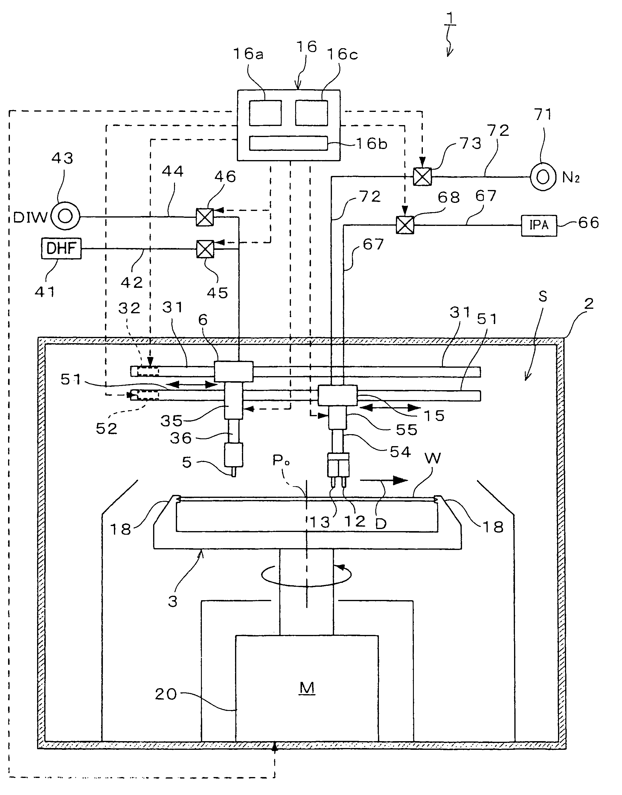
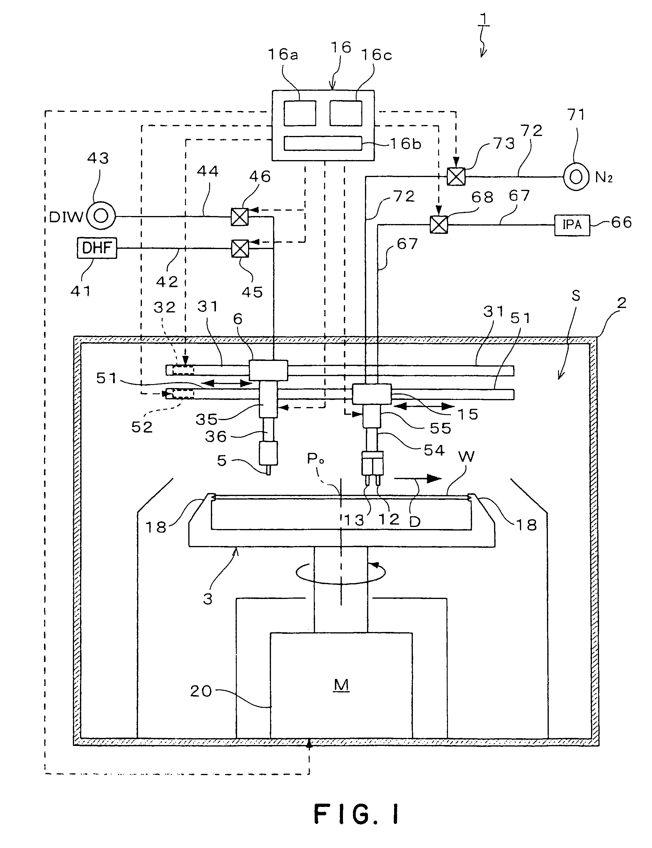
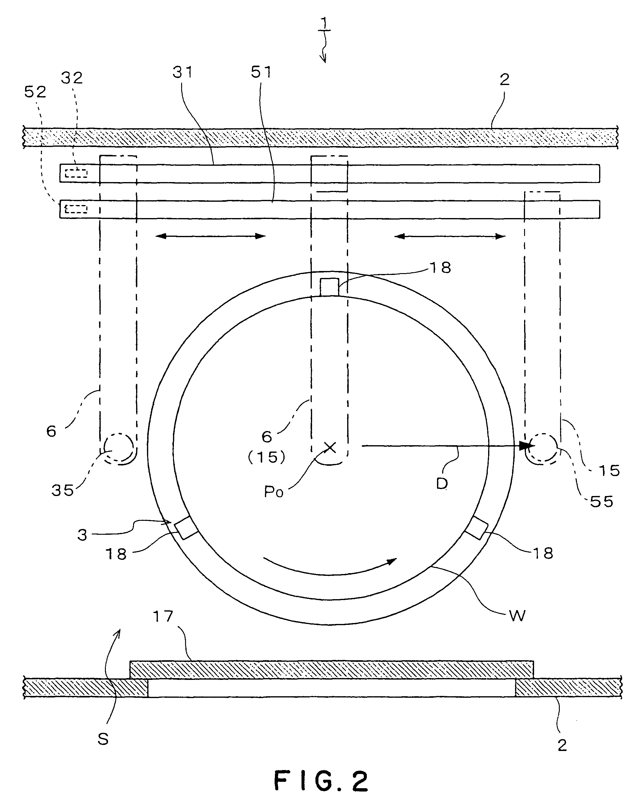
[0053]Preferred embodiments of the present invention will be described below, based on a substrate processing apparatus for cleaning an upper surface of a substantially disk-shaped silicon wafer W as a substrate.

[0054]As shown in FIG. 1, a substrate processing apparatus 1 in this embodiment includes a process vessel 2 in which a spin chuck 3 is disposed to substantially horizontally hold the wafer W and rotate the same. A liquid nozzle 5 is disposed for supplying to the wafer W a cleaning chemical liquid, such as DHF (dilute hydrofluoric acid), and a rinse liquid such as a deionized water (DIW). The liquid nozzle 5 is supported by a first support arm 6. A fluid nozzle 12 is disposed to supply, as a first fluid and a second fluid, a fluid having a higher volatility than that of a deionized water as a rinse liquid, such as an IPA (isopropyl alcohol) liquid. A drying gas nozzle 13 is disposed to supply, as a drying gas, an inert gas such as nitrogen gas (N2 gas). The fluid nozzle 12 an...


PUM

PropertyMeasurementUnit
moving speedaaaaaaaaaa
diameteraaaaaaaaaa
diameteraaaaaaaaaa

Abstract

A substrate (W) is processed with the use of a process liquid such as a deionized water. Then, a first fluid which is more volatile than the process liquid is supplied to an upper surface of the substrate (W) from a fluid nozzle (12) to form a liquid film. Next, a second fluid which is more volatile than the process liquid is supplied to the upper surface of the substrate (W) from the fluid nozzle (12), while the wafer (W) is being rotated. During this supply operation, a supply position (Sf) of the second fluid to the substrate (W) is moved radially outward from a rotational center (Po) of the substrate (W). As a result, it is possible to prevent the generation of particles on the substrate (W) after it is dried by using the first and second fluids.

Description

BACKGROUND OF THE INVENTION[0001]1. Field of the Invention[0002]The present invention relates to a substrate processing method for cleaning substrates such as semiconductor wafers and then drying the substrates, and a substrate processing method therefor.[0003]2. Background Art[0004]When manufacturing a semiconductor device, a processing apparatus is used for cleaning, with the use of a chemical liquid, a semiconductor wafer (referred to as “wafer” below) held on a spin chuck. In a cleaning process performed by such an apparatus, a process liquid such as a deionized water is supplied to a wafer, and thereafter the wafer is rotated to remove liquid droplets therefrom due to the centrifugal force so as to dry the wafer.[0005]Conventional methods for drying a wafer include methods for spraying a rotating wafer with an IPA (isopropyl alcohol) vapor, spraying a rotating wafer with atomized IPA, and supplying an IPA liquid to a rotating wafer. Another method for drying a wafer is, while s...

Claims


Application Information

Patent Timeline
Patent Type & Authority Patents(United States)
IPC IPC(8): B08B3/00B08B7/04
CPCB08B3/02B08B3/024B08B3/04H01L21/67051H01L21/6708Y10S134/902H01L21/304
Inventor SEKIGUCHI, KENJIUCHIDA, NORITAKATANAKA, SATORUOHNO, HIROKI
Owner TOKYO ELECTRON LTD
Why Eureka
Try Eureka