Devices and methods for automatically verifying, calibrating and surveying instruments for computer-assisted surgery

a technology of automatic verification and surveying instruments, applied in the field of automatic verification, calibration and surveying instruments for computer assisted surgery, can solve the problems of inability to deviate from the actual instrument, poor management, and inability to accurately represent the relationship between the actual instrument and the actual instrument, so as to increase the reliability of the process and reduce the effect of tim

Active Publication Date: 2010-10-05
BRAINLAB
View PDF10 Cites 172 Cited by
  • Summary
  • Abstract
  • Description
  • Claims
  • Application Information

AI Technical Summary

Benefits of technology

[0008]The present invention provides methods and devices for verifying, calibrating and surveying instruments for computer-assisted surgery that allow increased reliability in processes and occasional time reduction when employing navigated instruments for surgical procedures. Further, applicability is not limited to symmetrical or otherwise geometrically simple navigable instruments, but rather instruments with complex geometries also can be prepared for use in computer-assisted surgery.

Problems solved by technology

As soon as the stored geometric data, which mainly describe the functional elements in relation to the reference system, deviate from the actual geometry of the instrument (e.g., after the instrument has been damaged), this inevitably leads to an incorrect representation of the relation between the actual instrument and the anatomical structure to be treated (if the information stored in the database concerning the initial outline of the instrument continues to be used).
Matching the model data to the actual existing, possibly deviating instrument is not possible in verification.
Visibility problems and occasionally poor manageability when simultaneously positioning the instrument and the aid tend to extend the operation time.
Here, too, the visibility and manageability problems described above have a negative effect on the operation time.
Completely surveying functionally relevant structures of an instrument that is difficult to calibrate or verify represents a third method which, however, is not currently employed, since suitable aids are not available, nor could the procedures required be carried out by the operating staff within a justifiable time frame.

Method used


Image

  • Devices and methods for automatically verifying, calibrating and surveying instruments for computer-assisted surgery
  • Devices and methods for automatically verifying, calibrating and surveying instruments for computer-assisted surgery
  • Devices and methods for automatically verifying, calibrating and surveying instruments for computer-assisted surgery

Examples


Embodiment Construction

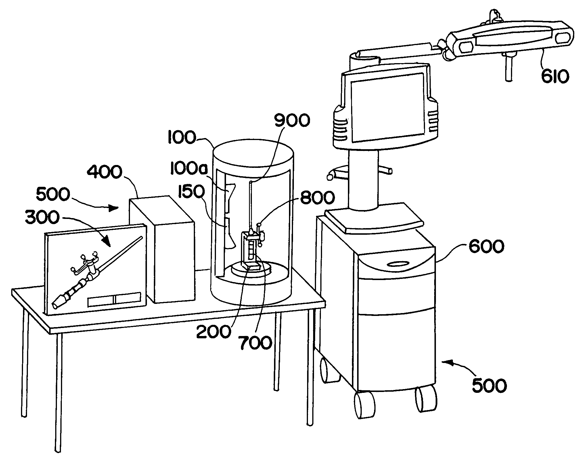
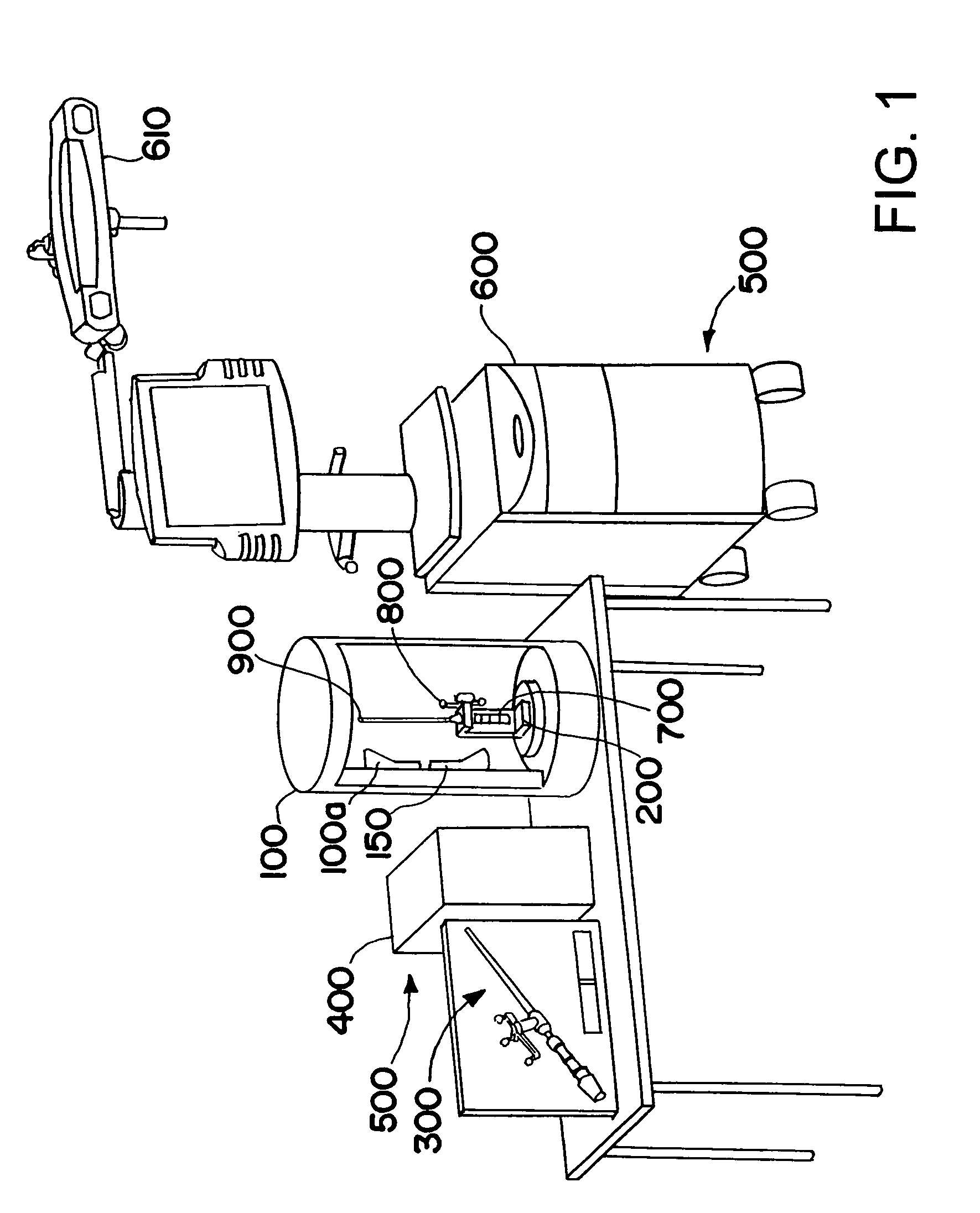
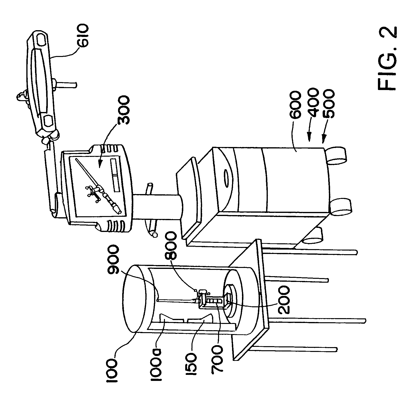
[0039]FIG. 1 shows an exemplary device for automatically verifying, calibrating and surveying an instrument, wherein a scanning device 100 and an instrument holding unit 200 are arranged in a cylindrical casing. An infrared camera unit 150 also can be attached in the casing for checking the condition, shape and / or quality of active or passive markers. For example, infrared radiation can be emitted onto the markers and the infrared camera unit 150 can detect the reflected infrared radiation. Alternatively, the infrared camera unit 150 can detect infrared radiation emitted by the markers. In the present example, the instrument 700 is positioned within the casing, preferably fixedly or non-movably in the instrument holding unit 200, wherein a reference system 800 is attached to the instrument 700, and the instrument 700 includes an instrument tip 900 as a functional element.

[0040]The scanning device 100 preferably senses the instrument optically, for example, by means of a laser or tac...


PUM


Abstract

A device and method for automatically verifying, calibrating and surveying a navigable surgical instrument, wherein by means of a scanning device, the geometry of the instrument, in particular the shape of the functional elements (e.g., tips) and their spatial position with respect to an attachable reference system, are detected. By means of a data processing unit, a three-dimensional model of the instrument is calculated from the detected information concerning the geometry of the instrument including the reference system, wherein verification, calibration or surveying is performed with the aid of the ascertained information concerning the geometry of the instrument.

Description

RELATED APPLICATION DATA[0001]This application claims priority of U.S. Provisional Application No. 60 / 701,567 filed on Jul. 22, 2005, which is incorporated herein by reference in its entirety.FIELD OF THE INVENTION[0002]The present invention relates to devices and methods for automatically verifying, calibrating and surveying instruments for use in computer-assisted surgery, wherein the geometry of the instrument and of a reference system formed by at least two markers and mountable permanently or detachably on the instrument, can be ascertained as a three-dimensional model with the aid of optical scanning methods and then further used by the navigation system. The precision and therefore speed of the scanning process is decisively controlled by the information which is already available and accessible for this instrument, wherein at least one verification, or for that matter a calibration or even a complete survey of the properties of the instrument, can or even has to be carried o...

Claims


Application Information

Patent Timeline
Patent Type & Authority Patents(United States)
IPC IPC(8): G06K9/00A61B5/05
CPCA61B19/52A61B19/5244A61B2017/00725A61B2019/448A61B2019/502A61B2019/5255A61B34/20A61B90/36A61B90/98A61B2034/102A61B2034/2055
Inventor NEUBAUER, TIMOPLASSKY, NORMAN
Owner BRAINLAB
Why Eureka
Try Eureka