Medical system calibration with static metal compensation

a technology of static metal compensation and medical system, applied in the field of noncontact electromagnetic medical system, can solve the problem of no known system or method, and achieve the effect of reducing variability in calibration

Active Publication Date: 2010-10-05
BIOSENSE
View PDF39 Cites 43 Cited by
  • Summary
  • Abstract
  • Description
  • Claims
  • Application Information

AI Technical Summary

Benefits of technology

[0029](i) setting the added distance component (dx, dy, dz) by decreasing the value of the added distance component if the position difference is not within the error limit and repeating steps (d)-(g) along the same coordinate axis.
[0030]The method also includes completing the calibration method for the entire mapping volume in accordance with the steps outlined above. Although, the error limit can be any reasonable error range, it is preferable that the error limit be ≦1 mm for the greatest accuracy effects. Additionally, the sensor is stepped or moved a distance ranging from about 2 cm to about 3 cm. Moreover, with respect to the stepping of the sensor, the distance moved should remain constant to eliminate variability in the calibration. Also, step (i) is accomplished by decreasing the value of the added distance component through division by a factor of two (Xi+dx / 2, Yi+dy / 2, Zi+dz / 2).

Problems solved by technology

Interestingly, although this reference discloses that frequency multiplexing can be utilized in order to significantly increase the operating speed of the position system, it clearly indicates that there are disadvantages to this type of approach due to its complexity.
It is also important to note that although this reference teaches a single axis sensor position and orientation tracking system, it does not address any specific method for calibrating the system.
Accordingly, to date, there is no known system or method that provides for a electromagnetic position sensor single axis system and method that is capable of being simultaneously driven through frequency multiplexing utilizing a novel exact solution technique and a novel calibration method.

Method used


Image

  • Medical system calibration with static metal compensation
  • Medical system calibration with static metal compensation
  • Medical system calibration with static metal compensation

Examples


first embodiment

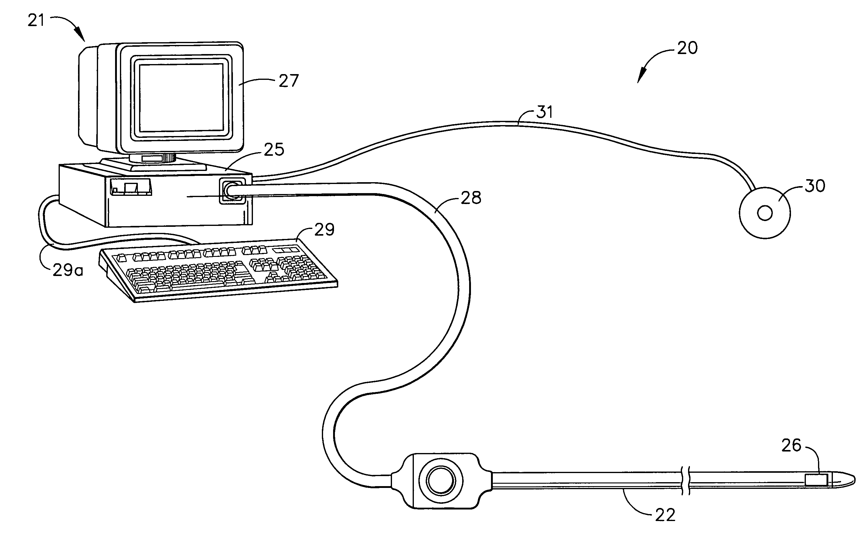
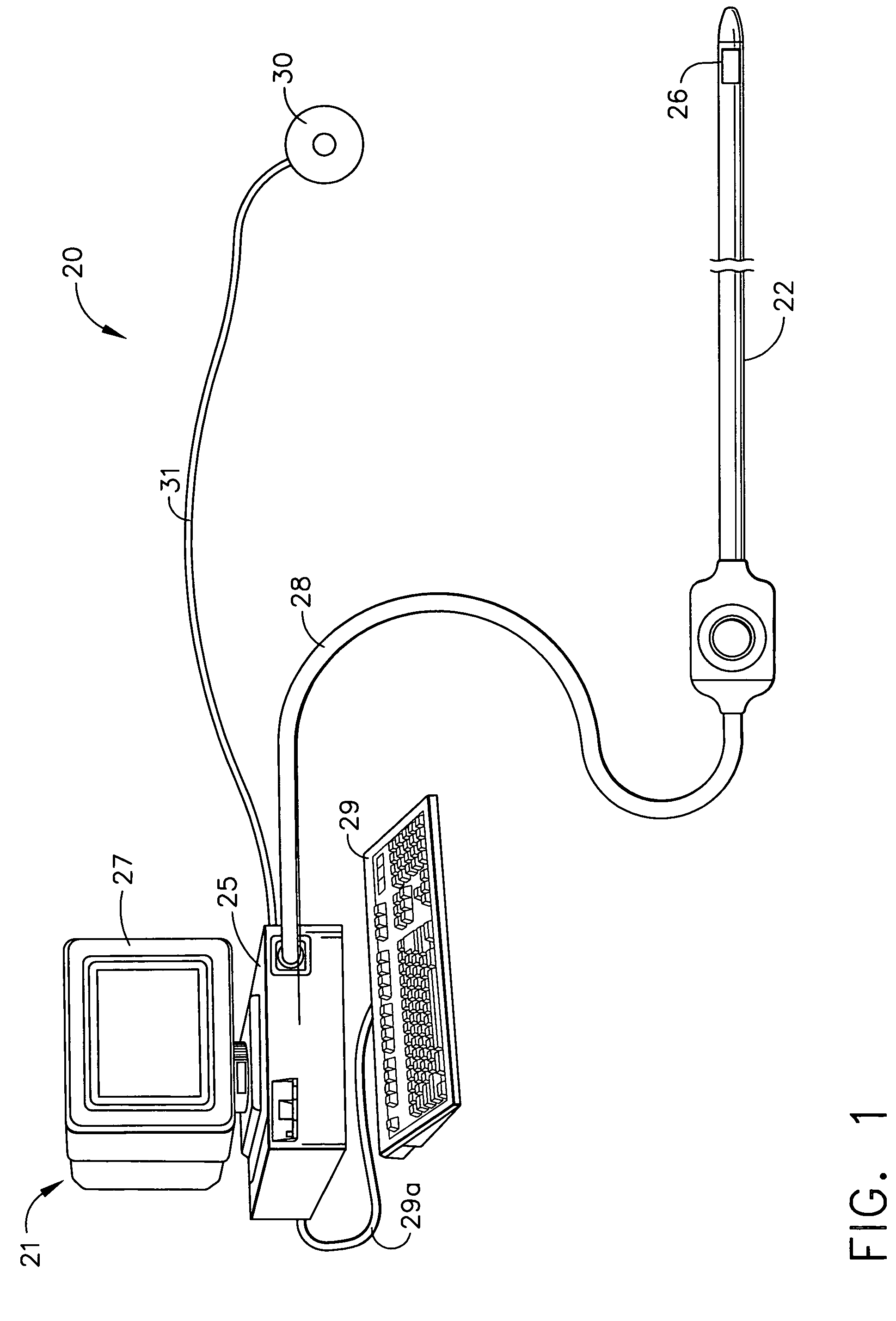
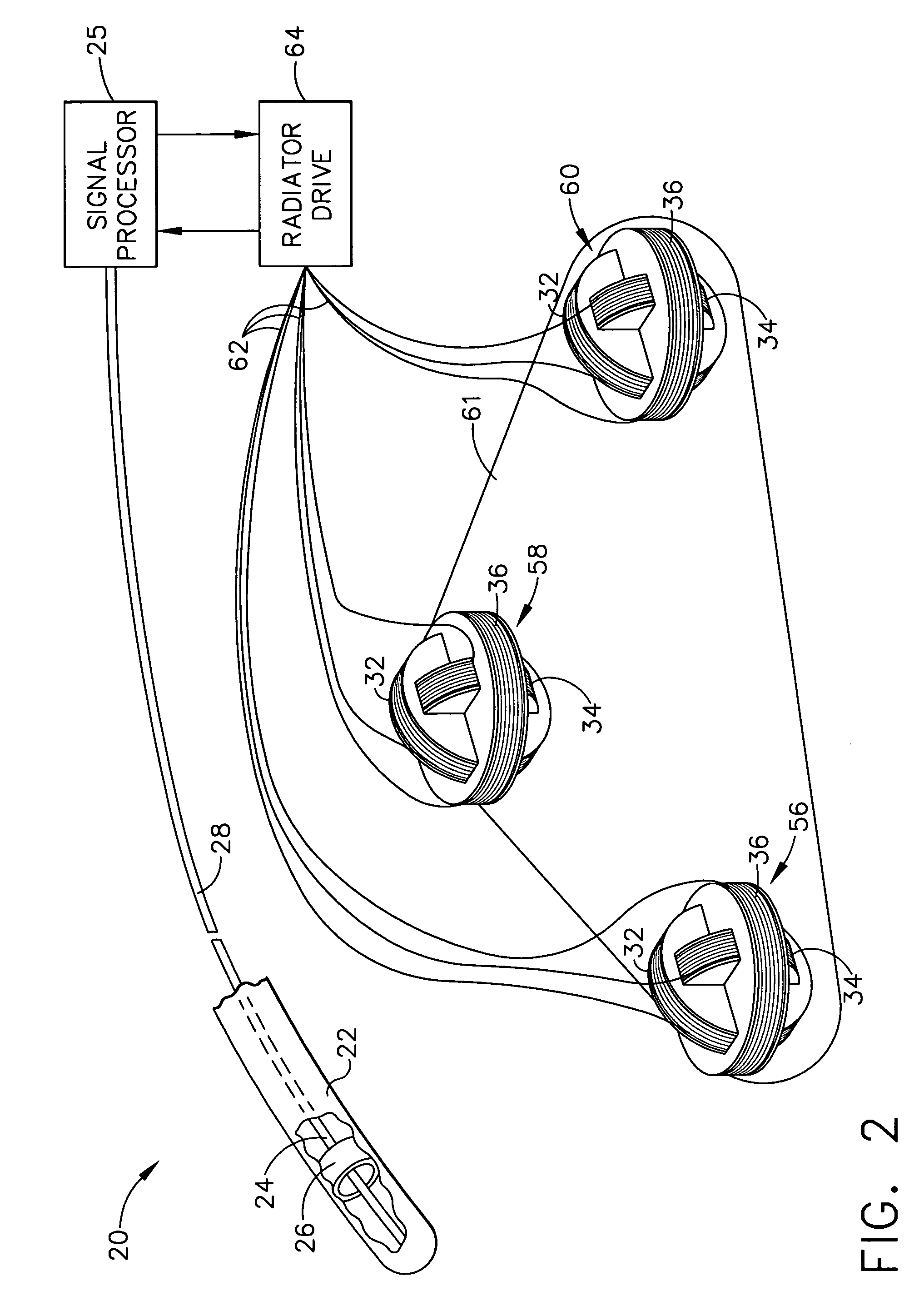
[0063]System 20 further comprises radiator elements or coils 32, 34, 36, 38, 40, 42, 44, 46, and 48 (also known as generator coils). In one embodiment, the coils are wound in sets of three orthogonal and concentric coils forming radiators 56, 58, and 60, respectively. Preferably, the coils 32, 34, 36, 38, 40, 42, 44, 46, and 48 are each wound around a support member such as a spool. In this first embodiment, each radiator 56, 58 and 60 has three coils that are co-located. Accordingly, the coils of each radiator are concentric with each other and mutually orthogonal with each other. The concentric arrangement is accomplished by having each coil within a particular radiator shaped such that the coils with their respective support member each have a different diameter. For instance, by way of example with respect to radiator 56, coil 36 accommodates and receives coils 32 and 34 and coil 34 accommodates and receives coil 32. Thus, coil 36 (with its support member) has a diameter that is...

fourth embodiment

[0068]FIG. 9 illustrates a radiator arrangement in accordance with the present invention. In this embodiment, radiators 56c, 58c and 60c comprise a co-located arrangement for the radiator coils 32, 34, 36, 38, 40, 42, 44, 46 and 48 respectively wherein the coils of each radiator are concentric with respect to each other similar to the radiator embodiment of FIG. 2. However, the coils of each radiator 56c, 58c and 60c are are not orthogonal to each other. Again, the only limitation to the coil orientations is that one coil is not parallel to another coil in a particular radiator arrangement 56c, 58c and 60c.

[0069]Position and Orientation Method

[0070]FIG. 3 is a schematic flow chart illustrating a method and associated algorithmic components for determining the coordinates of sensing coil 26, in accordance with a preferred embodiment of the present invention. The general method steps will be described below and the specific steps of the novel algorithm will be described in detail lat...

second embodiment

[0198]the calibration method according to the present invention utilizes extrapolation of the magnetic field at the next point. As shown in FIG. 13, in particular, first, the metallic object is placed within the intended mapping volume. Again, the robot arm 110 positions the sensor 100 at the first point 210 (starting or first position Xi, Yi, Zi) and the magnetic field at this first point is read and measured by the signal processor 25 to determine the first coordinate position. Next, the signal processor 25, extrapolates the magnetic field at the next or second point 220, e.g. next or second coordinate position (next vertex of mapping cube 200a which is the extrapolated point) defined as (Xi=Xi+dx, Yi=Yi+dy, Zi=Zi+dz) which includes the added distance component dx, dy, dz as appropriate. In this case, the added distance component (dx) is a 3 cm distance along the X coordinate axis.

[0199]Once the magnetic field for the second point (the next point) is extrapolated, the location coo...


PUM


Abstract

A method for calibrating a medical system capable of generating a magnetic field for tracking a position of a medical device has various steps such as defining a mapping volume within the generated magnetic field and placing a metallic object within the mapping volume. A sensor is aligned at a first point within the mapping volume and the magnetic field at the first point is measured with the sensor to establish a first coordinate position (Xi, Yi, Zi). An interpolation technique in one embodiment and an extrapolation technique in another embodiment are used in the calibration method.

Description

FIELD OF THE INVENTION[0001]The present invention relates generally to object tracking systems, and specifically to non-contact, electromagnetic medical systems and methods for tracking the position and orientation of an object. The present invention is also directed to a novel calibration method for electromagnetic-based medical tracking systems that can account for the effects of interference from nonmoving metallic objects.BACKGROUND OF THE INVENTION[0002]Non-contact methods of determining the position of an object based on generating a magnetic field and measuring its strength at the object are well known in the art. For example, U.S. Pat. No. 5,391,199, and PCT patent application publication WO 96 / 05768, which are incorporated herein by reference, describe such systems for determining the coordinates of a medical probe or catheter inside the body. These systems typically include one or more coils within the probe, generally adjacent to the distal end thereof, connected by wires...

Claims


Application Information

Patent Timeline
Patent Type & Authority Patents(United States)
IPC IPC(8): A61B5/05A61B1/00A61B5/06G01B7/00A61B19/00G01V13/00
CPCA61B5/06A61B19/5244G01V13/00A61B2019/5251H01F2005/027A61B34/20A61B2034/2051A61B5/062
Inventor GOVARI, ASSAF
Owner BIOSENSE
Why Eureka
Try Eureka