Storage water heater

a storage water heater and water tank technology, applied in the field of storage water heaters, can solve the problems of unnecessarily reducing the temperature of the hot-water storage chamber 102, the inefficiency of the heating means of tap water supplied into the hot-water tank, and the inability to efficiently lead the hot-water tank to the heating means, etc., to achieve the effect of increasing heat efficiency, increasing thermal efficiency, and increasing thermal efficiency

Active Publication Date: 2010-10-12
PALOMA
View PDF12 Cites 10 Cited by
  • Summary
  • Abstract
  • Description
  • Claims
  • Application Information

AI Technical Summary

Benefits of technology

[0015]In the storage water heater of the invention according to a second aspect, in addition to the effects of the invention according to the first aspect, the following operation effects can be achieved. That is, tap water which is supplied into the hot-water tank is discharged from the outlet of the water supply pipe toward the inlet of the lead-in pipe provided so as to be opposed to the outlet of the water supply pipe on the same axis. Therefore, when tap water is supplied, the tap water is preferentially led to the heating means. That is, the tap water lower in temperature than the warm water pre-stored in the hot-water tank is preferentially heated, thereby further increasing heat efficiency.
[0016]In the storage water heater of the invention according to a third aspect, in addition to the effects of the invention according to the first or second aspect, the following effects can be achieved. That is, tap water supplied into the hot-water tank is discharged downward from the outlet of the water supply pipe that is open downward. Since the tap water has a density higher than that of warm water pre-stored in the hot-water tank, the tap water stays below the outlet of the water supply pipe. The tap water staying at a lower portion of the hot-water tank is led to the heating means through the inlet of the lead-in pipe that is open upward below the outlet of the water supply pipe, thereby increasing heat efficiency. In particular, when the outlet of the water supply pipe and the inlet of the lead-in pipe are provided so as to be vertically opposed on the same axis, tap water is smoothly led to the inlet of the lead-in pipe from the outlet of the water supply pipe. In this case, thermal efficiency can be further increased.
[0017]In the storage water heater of the invention according to a fourth aspect, in addition to the effects of the invention according to any of the first to third aspects, the following effects can be achieved. That is, firstly, when the inlet of the lead-in pipe is open in a shape being widened upward, low-temperature water with a high density smoothly flows downward from the inlet opening with a wide area toward the inside of the lead-in pipe. Therefore, the low-temperature water is led to the heating means, thereby increasing thermal efficiency. In particular, when the outlet of the water supply pipe and the inlet of the lead-in pipe are provided so as to be opposed to each other on the same axis, the resistance at the inlet of the lead-in pipe is small. Therefore, the flow of the tap water discharged from the outlet of the water supply pipe is led to the lead-in pipe without disturbance. With this, mixture of warm water inside the hot-water tank can be reduced, thereby further increasing heat efficiency.
[0018]In the storage water heater of the invention according to a fifth aspect, in addition to the effects of the invention according to any of the first to fourth aspects, the following effects can be achieved. Tap water is sent into the hot-water tank from the outlet of the water supply pipe positioned on the center axis of the hot-water tank, and hot water at a lower portion in the hot-water tank is taken out from the inlet of the lead-in pipe at the bottom portion or the lower portion of the hot-water tank on the center axis. Therefore, tap water supplied to the inside of the hot-water tank does not stay for a long time. Therefore, thermal efficiency of the entire storage water heater can be increased.

Problems solved by technology

However, in the storage water heater as described above, when the temperature of the hot water in the hot-water storage chamber 102 is high, a difference between the temperature of exhaust gas passing through the exhaust path 105 and the temperature of hot water in the hot-water storage chamber 102 becomes small, thereby posing a problem that thermal efficiency is decreased.
Moreover, in a wait state where the gas burner 113 is not operated for burning, the temperature in the exhaust path 105 becomes lower than the temperature of the hot water in hot-water storage chamber 102, and heat is dissipated from the inside of the hot-water storage chamber 102 to the outside via the exhaust path 105, thereby posing a problem that the temperature in the hot-water storage chamber 102 decreases unnecessarily.
Still further, although a storage water heater with a heating means provided outside of a hot-water tank has been known, tap water supplied into the hot-water tank has not yet been efficiently led to the heating means so far.
There is also a problem that, when tap water is supplied into the hot-water tank, it takes a certain time until the temperature detector detects a decrease in water temperature after the temperature of the hot water in the hot-water tank falls.

Method used


Image

  • Storage water heater
  • Storage water heater
  • Storage water heater

Examples


Embodiment Construction

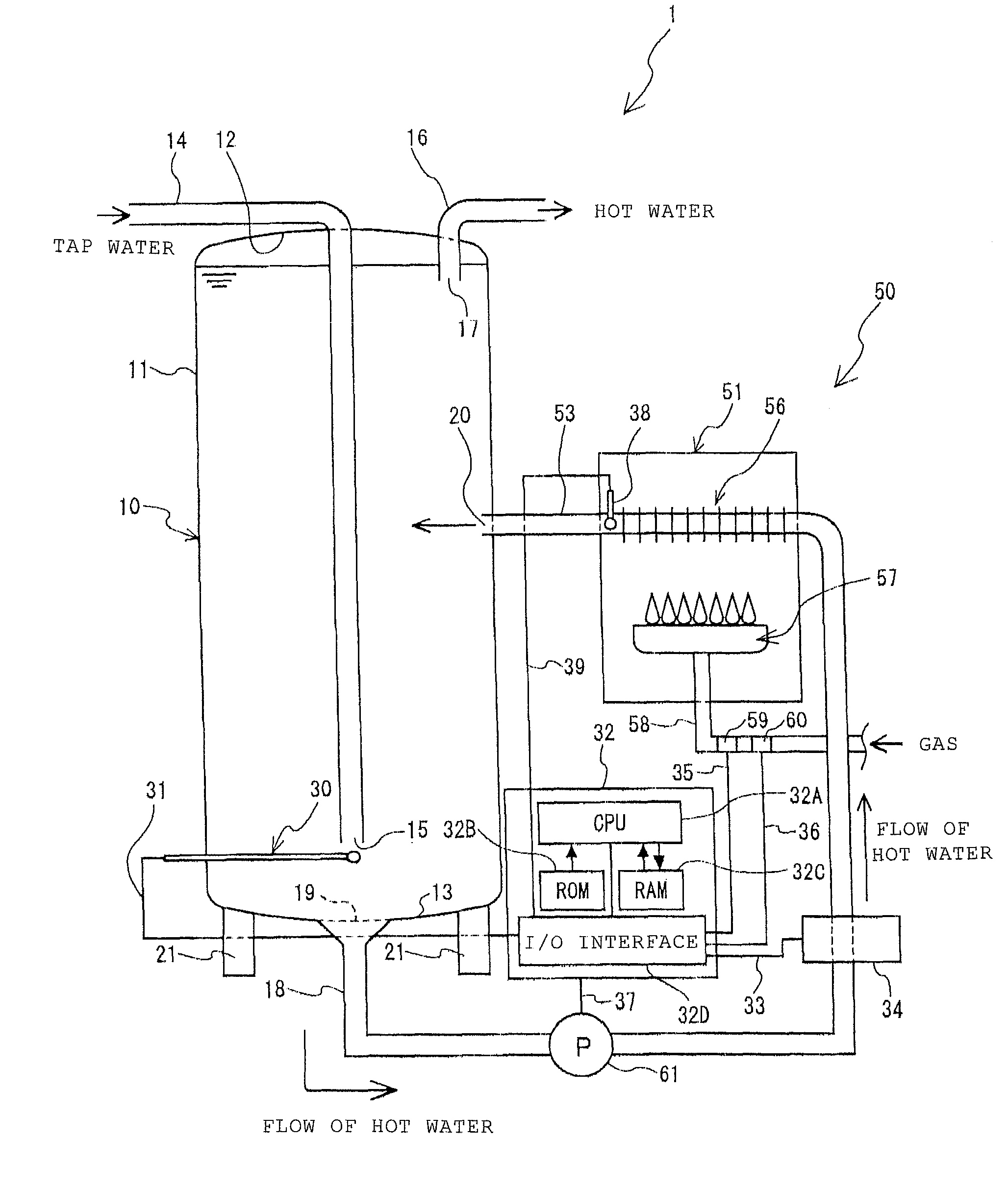
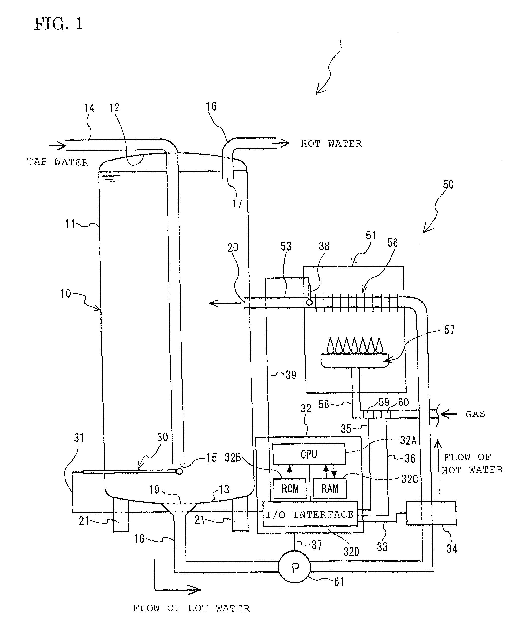
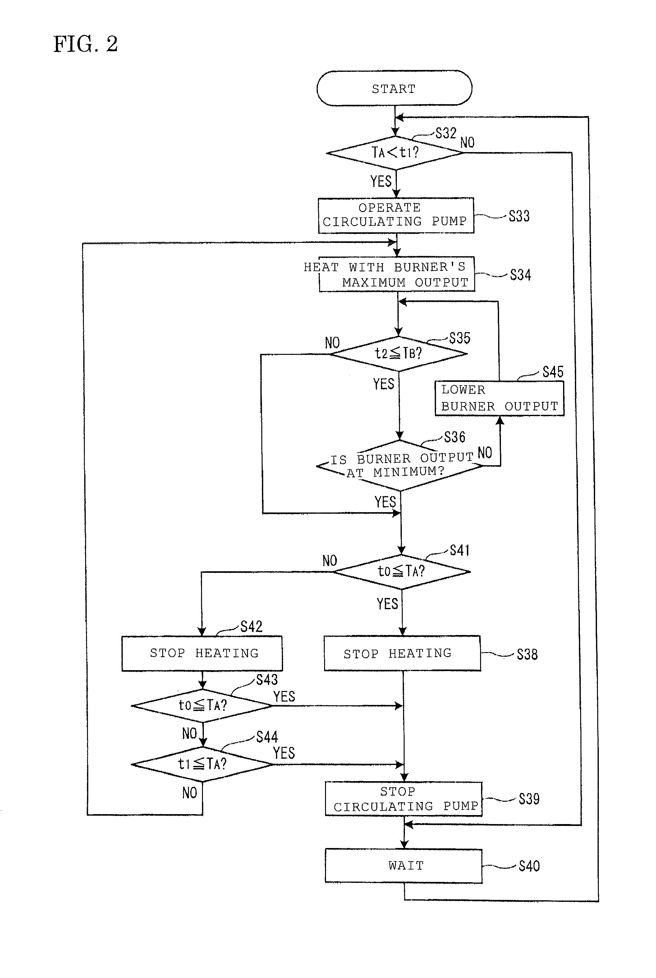
[0023]A storage water heater 1 according to one embodiment of the present invention is described below based on the drawings. FIG. 1 is a schematic configuration drawing of the storage water heater 1 of the present embodiment, and FIG. 2 is a flowchart of a control operation of a controller 32 in the present embodiment.

[0024]First, the storage water heater 1 is schematically described. As illustrated in FIG. 1, the storage water heater 1 is formed mainly of a hot-water tank 10 for storing hot water, a circulating heating unit 50 that circulates and heats the hot water stored in the hot-water tank 10, and a controller 32 that controls the operation of the storage water heater 1.

[0025]The hot-water tank 10 is first described. As illustrated in FIG. 1, the hot-water tank 10 is a tank made of metal or resin with its side surface being in cylindrical shape. The hot-water tank 10 has a spherical lower panel 13 closing a lower end and swelling downward and a spherical upper panel 12 closin...


PUM


Abstract

To provide a storage water heater capable of increasing thermal efficiency and quickly boiling when tap water is supplied into a hot-water tank. A storage water heater can heat low-temperature water having a high density because hot water in a hot-water tank is led from a lead-in pipe positioned at the bottom of the hot-water tank to a gas heater. Also, a water supply pipe outlet and a lead-in pipe inlet are provided so as to be opposed to each other on the same axis. Therefore, when tap water is supplied from a water supply pipe, the tap water lower in temperature than the hot water in the hot-water tank is preferentially led to the gas heater. With this, hot water at the lowest temperature in the hot-water tank can be selectively heated, thereby increasing thermal efficiency.

Description

BACKGROUND OF THE INVENTION[0001]This application is based on Japanese Patent Application Number 2006-028260 filed on Feb. 6, 2006, the entirety of which is incorporated by reference.FIELD OF THE INVENTION[0002]The present invention relates to a storage water heater and, in detail, to a storage water heater with a hot-water tank.DESCRIPTION OF THE RELATED ART[0003]Conventionally, a storage water heater with a hot-water tank for storing hot water has been known. Such a storage water heater includes, for example, a hot-water storage chamber 102 at an upper portion and a combustion chamber 103 at a lower portion in a hollow cylindrical body 101, as illustrated in FIG. 3. The hot-water storage chamber 102 includes a temperature detector 300 below a center portion. The combustion chamber 103 has an air inlet 104 through which air is supplied to the inside and an exhaust path 105 through which combustion gas in the combustion chamber 103 is exhausted to the outside, the path penetrating t...

Claims


Application Information

Patent Timeline
Patent Type & Authority Patents(United States)
IPC IPC(8): F22B1/02
CPCF24H9/2035F24H15/36F24H15/156F24H15/414F24H15/225F24H15/281F24H15/395F24H15/219F24H15/31
Inventor KOBAYASHI, TOSHIHIRO
Owner PALOMA
Why Eureka
Try Eureka