Photoelectric conversion device and image capturing device with variable amplifier for amplifying signal by a selected gain

a conversion device and amplifier technology, applied in the field of photoelectric conversion devices and image capturing devices, can solve the problems of increasing fixed-pattern noise, increasing read rate, and two requests cannot be satisfied simultaneously, and achieve the effect of suppressing fixed-pattern noise and increasing read ra

Inactive Publication Date: 2010-10-12
CANON KK
View PDF30 Cites 45 Cited by
  • Summary
  • Abstract
  • Description
  • Claims
  • Application Information

AI Technical Summary

Benefits of technology

[0008]The present invention has been made to overcome the conventional drawbacks, and has as its object to increase the read rate while suppressing fixed-pattern noise in an arrangement capable of changing the gain of an amplifier unit which amplifies a signal output from a pixel to a pixel signal line.
[0015]The present invention can increase the read rate while suppressing fixed-pattern noise in an arrangement capable of changing the gain of an amplifier unit which amplifies a signal output from a pixel to a pixel signal line.

Problems solved by technology

However, a solid-state image sensor in which the column amplifier switches the gain suffers the following problem in increasing the read rate.
However, a small holding capacitor leads to large relative variations between the capacitance values of holding capacitors, increasing fixed-pattern noise.
However, as the read rate increases, these two requests cannot be satisfied simultaneously.

Method used


Image

  • Photoelectric conversion device and image capturing device with variable amplifier for amplifying signal by a selected gain
  • Photoelectric conversion device and image capturing device with variable amplifier for amplifying signal by a selected gain
  • Photoelectric conversion device and image capturing device with variable amplifier for amplifying signal by a selected gain

Examples


first embodiment

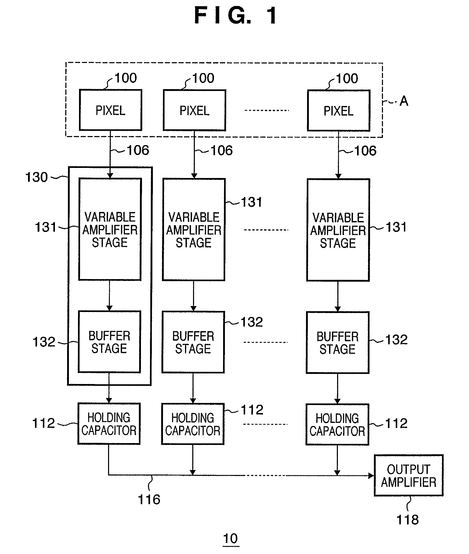
[0027]FIG. 1 is a block diagram showing the schematic arrangement of a photoelectric conversion device (solid-state image sensor) 10 according to the first embodiment of the present invention. Each pixel 100 includes a photoelectric converter such as a photodiode, and outputs a signal to a vertical output line (first pixel output line) 106 based on a signal obtained by photoelectrically converting incident light. Pixels 100 arrayed in a plurality of rows x a plurality of columns form pixel array A. A vertical scanning circuit (not shown) selects a row while a horizontal scanning circuit (not shown) selects a column. FIG. 1 shows pixels 100 arrayed in one row x a plurality of columns for descriptive convenience.

[0028]A column amplifier (amplifier unit) 130 receives a signal output to the vertical output line 106. The column amplifier 130 includes a variable amplifier stage 131, and a buffer stage 132 arranged on the output side of the variable amplifier stage 131. The variable amplif...

second embodiment

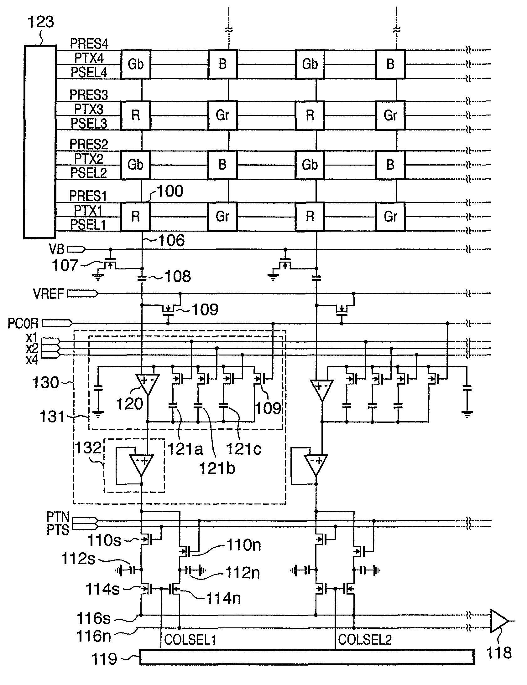
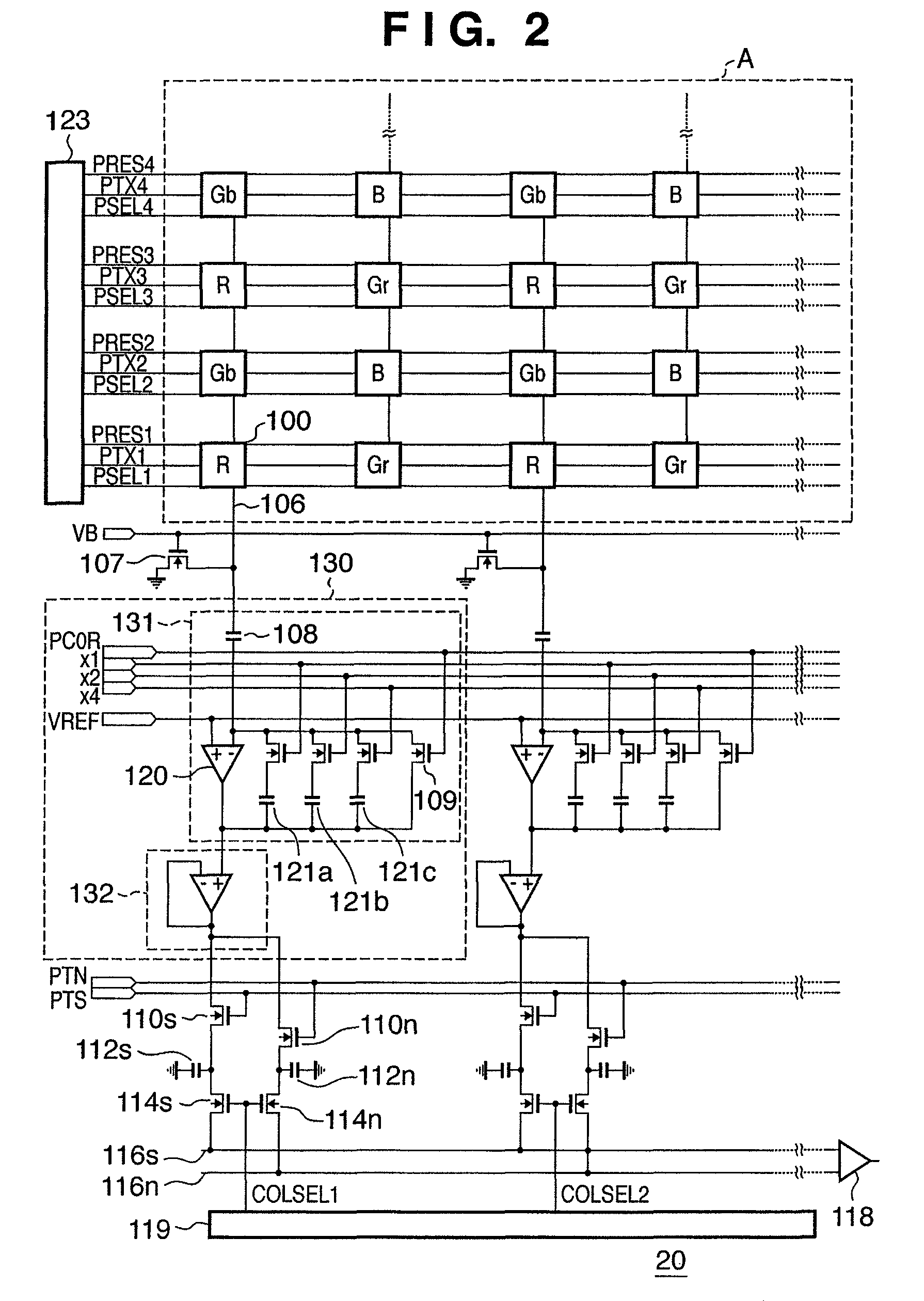
[0035]FIG. 2 is a circuit diagram showing the schematic arrangement of a photoelectric conversion device (solid-state image sensor) 20 according to the second embodiment of the present invention. Pixels 100 arrayed in a plurality of columns x a plurality of rows form pixel array A. Color filters R, Gr, Gb, and B in the Bayer array are formed on the pixels 100. In pixel array A, basic units each of 2×2 pixels are two-dimensionally arrayed.

[0036]A pixel having an R color filter will be called an R pixel; a pixel having a Gr color filter, a Gr pixel; a pixel having a Gb color filter, a Gb pixel; and a pixel having a B color filter, a B pixel.

[0037]Signals from R and Gb pixels are read out by a readout circuit arranged below pixel array A. Signals from B and Gr pixels are read out by a readout circuit (not shown) arranged above pixel array A.

[0038]FIG. 3 is an equivalent circuit diagram of one pixel 100. The transfer pulse PTX drives a transfer switch 102. The reset pulse PRES drives a ...

third embodiment

[0055]FIG. 6 is a circuit diagram showing the schematic arrangement of a photoelectric conversion device (solid-state image sensor) 30 according to the third embodiment of the present invention. The photoelectric conversion device 30 according to the third embodiment is different from the photoelectric conversion device 20 according to the second embodiment in that a buffer stage 132 in a column amplifier 130 is formed from a source follower.

[0056]As a feature of the photoelectric conversion device 30 according to the third embodiment, the number of elements which form the buffer stage 132 is small. As another feature, when a holding capacitor 112 is charged with a column amplifier output corresponding to the saturation light quantity, it is possible to charge the holding capacitor 112 regardless of the constant current value.

[0057]When a signal written in the holding capacitor increases in voltage along with an increase in light quantity, the source follower which forms the buffer ...


PUM


Abstract

A photoelectric conversion device includes a pixel output line, a pixel which outputs a signal to the pixel output line, an amplifier unit which amplifies the signal output to the pixel output line, and a holding capacitor which holds the signal output from the amplifier unit. The photoelectric conversion device outputs a pixel signal based on the signal held by the holding capacitor. The amplifier unit includes a variable amplifier stage which amplifies a signal output to the pixel output line at a gain selected from a plurality of gains, and a buffer stage which amplifies the signal output from the variable amplifier stage, the amplified signal being held by the holding capacitor to hold the signal.

Description

BACKGROUND OF THE INVENTION[0001]1. Field of the Invention[0002]The present invention relates to a photoelectric conversion device and image capturing device.[0003]2. Description of the Related Art[0004]These days, CMOS sensors have prevailed for digital cameras. One main reason is that the CMOS sensor can achieve a high S / N under ISO sensitivity conditions varying from ISO 100 to ISO 1600. A high-S / N CMOS sensor is effectively implemented using a column amplifier having a gain switching function. This is because random noise can be suppressed much more by switching the gain in a column amplifier of a narrow band (operation frequency of about several hundred kHz) than by applying the gain in a final output amplifier of a wide band (operation frequency of several MHz to several ten MHz). Generally when amplifying an analog signal, increasing the gain at as early a stage as possible is effective against random noise and fixed-pattern noise.[0005]FIGS. 8 and 9 are circuit diagrams exce...

Claims


Application Information

Patent Timeline
Patent Type & Authority Patents(United States)
IPC IPC(8): H04N3/15H04N5/335H04N5/217H01L27/146H04N5/365H04N5/369H04N5/374H04N5/3745H04N5/378
CPCH04N5/3651H04N5/3742H04N5/378H04N25/671H04N25/767H04N25/75
Inventor HIYAMA, HIROKIOGURA, MASANORI
Owner CANON KK
Why Eureka
Try Eureka