X-ray microscope with switchable x-ray source

a switchable x-ray source and microscope technology, applied in the direction of material analysis using wave/particle radiation, instruments, nuclear engineering, etc., can solve the problems of excessive downtime of x-ray imaging instruments, more frequent maintenance intervals, and relatively long downtime of synchrotron radiation facilities

Active Publication Date: 2010-10-12
CARL ZEISS X RAY MICROSCOPY
View PDF2 Cites 46 Cited by
  • Summary
  • Abstract
  • Description
  • Claims
  • Application Information

AI Technical Summary

Problems solved by technology

On drawback of synchrotron radiation facilities is the relatively long down-time compared with tabletop x-ray sources.
While a tabletop source can typically run continuously between annual or semi-annual maintenance intervals, synchrotrons typically require more frequent maintenance intervals with long shutdown times. These maintenance requirements lead to excessive down-time of x-ray imaging instruments.

Method used


Image

  • X-ray microscope with switchable x-ray source
  • X-ray microscope with switchable x-ray source

Examples


Embodiment Construction

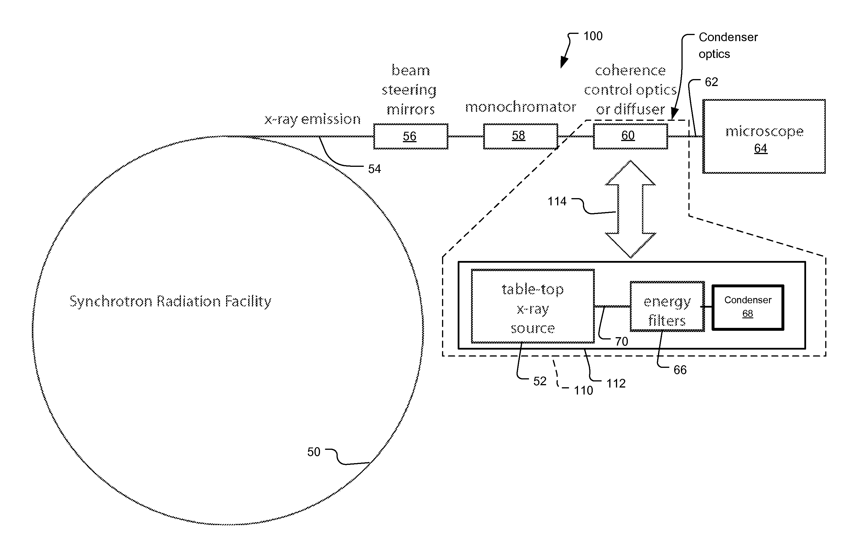
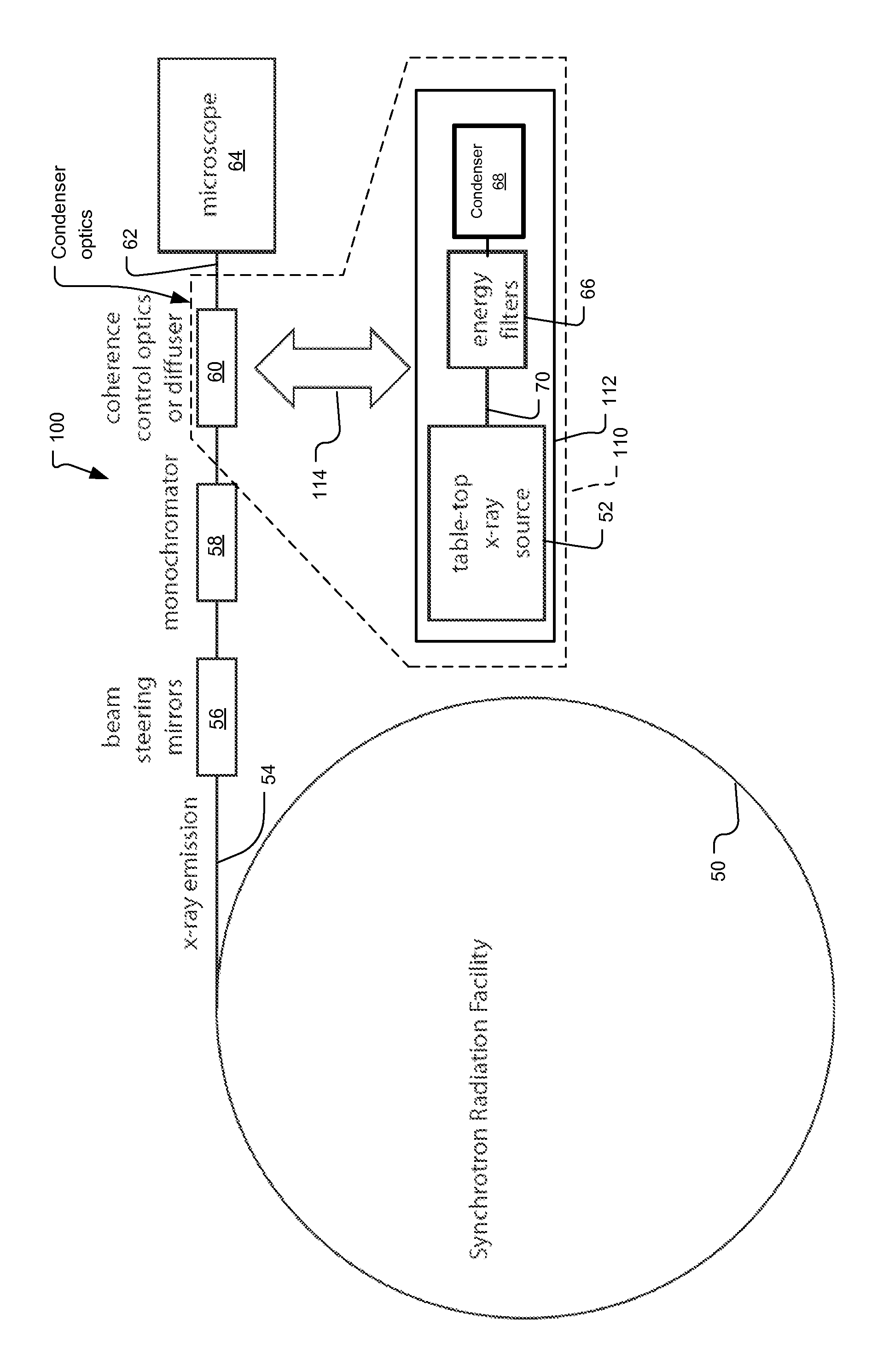
[0011]FIG. 1 shows x-ray microscope system 100 using a table-top source 52 and synchrotron source 50 according to the principals of the present invention.

[0012]Synchrotrons generate highly collimated x-ray radiation with tunable energy. They are excellent sources for high-resolution x-ray microscopes. The x-ray radiation 54 generated from the synchrotron 50 is controlled and aligned by the beam-steering mirrors 56. It then reaches a monochromator 58 to select a narrow wavelength band. The monochromator 58 is typically gratings or a crystal monochromator to disperse the x-ray beam 54 based on wavelength. When combined with entrance and exit slits, it will select a specific energy from the dispersed beam. The energy resolution will depend on the grating period, distance between the slits and grating, and the slit sizes.

[0013]Also included is the table-top x-ray source 52. Typically this source is a rotating anode, microfocus, or x-ray tube source.

[0014]Either of the table-top x-ray so...


PUM

PropertyMeasurementUnit
absorptive energyaaaaaaaaaa
microscopyaaaaaaaaaa
brightnessaaaaaaaaaa

Abstract

An x-ray imaging system uses a synchrotron radiation beam to acquire x-ray images and at least one integrated x-ray source. The system has an imaging system including sample stage controlled by linear translation stages, objective x-ray lens, and x-ray sensitive detector system, placed on a fixed optical table and a mechanical translation stage system to switch x-ray sources when synchrotron radiation beam is not available.

Description

RELATED APPLICATIONS[0001]This application claims the benefit under 35 USC 119(e) of U.S. Provisional Application Nos. 61 / 035,479, filed on Mar. 11, 2008 and 61 / 035,481, filed on Mar. 11, 2008, both of which are incorporated herein by reference in their entirety.[0002]This application relates to U.S. application Ser. No. 12 / 401,750 filed on Mar. 11, 2009.BACKGROUND OF THE INVENTION[0003]X-ray imaging has become an important part of our lives since its invention in the 19th century. The imaging techniques that are used in medical imaging and security inspection systems are usually projection systems that record the shadow radiograph behind the subject. In the 1980s, microscopy techniques based on x-ray lenses have emerged to dramatically improve the resolution of x-ray imaging to tens of nanometers.[0004]The majority of these x-ray imaging systems use traditional table top electron-bombardment x-ray sources, but sources with much higher brightness and different spectral characteristi...

Claims


Application Information

Patent Timeline
Patent Type & Authority Patents(United States)
IPC IPC(8): G01N23/04
CPCG21K7/00H01J2235/00
Inventor WU, ZIYUYUN, WENBINGZHU, PEIPINGWANG, YUXINYUAN, QINGXITKACHUK, ANDREIHUANG, WANXIAFESER, MICHAEL
Owner CARL ZEISS X RAY MICROSCOPY
Why Eureka
Try Eureka