Portable powered air conditioner

a portable, cooling technology, applied in space heating and ventilation, lighting and heating apparatus, heating types, etc., can solve the problems of not being self-sufficient, and the portable air conditioner of the travis patent does not utilize an absorption refrigeration system

Inactive Publication Date: 2010-10-19
HEATER TIM +5
View PDF9 Cites 15 Cited by
  • Summary
  • Abstract
  • Description
  • Claims
  • Application Information

AI Technical Summary

Problems solved by technology

However, the portable cooler of the Redfern Patent is powered by the air conditioning system of a vehicle, which is not a self-sufficient system.
However, the Eddins Patent does not discuss how to make or operate the portable air conditioner, or more specifically, a portable air conditioner that utilizes an absorption refrigeration principal.
However, the portable air conditioner of the Travis Patent does not utilize an absorption refrigeration system that is powered by heat produced from a propane gas source.
However, the portable air conditioner of the Hodges Patent requires a portable electrical source in order to operate, as opposed to a portable refrigeration system utilizing an absorption refrigeration system that requires little or no electricity.

Method used


Image

  • Portable powered air conditioner
  • Portable powered air conditioner
  • Portable powered air conditioner

Examples


first embodiment

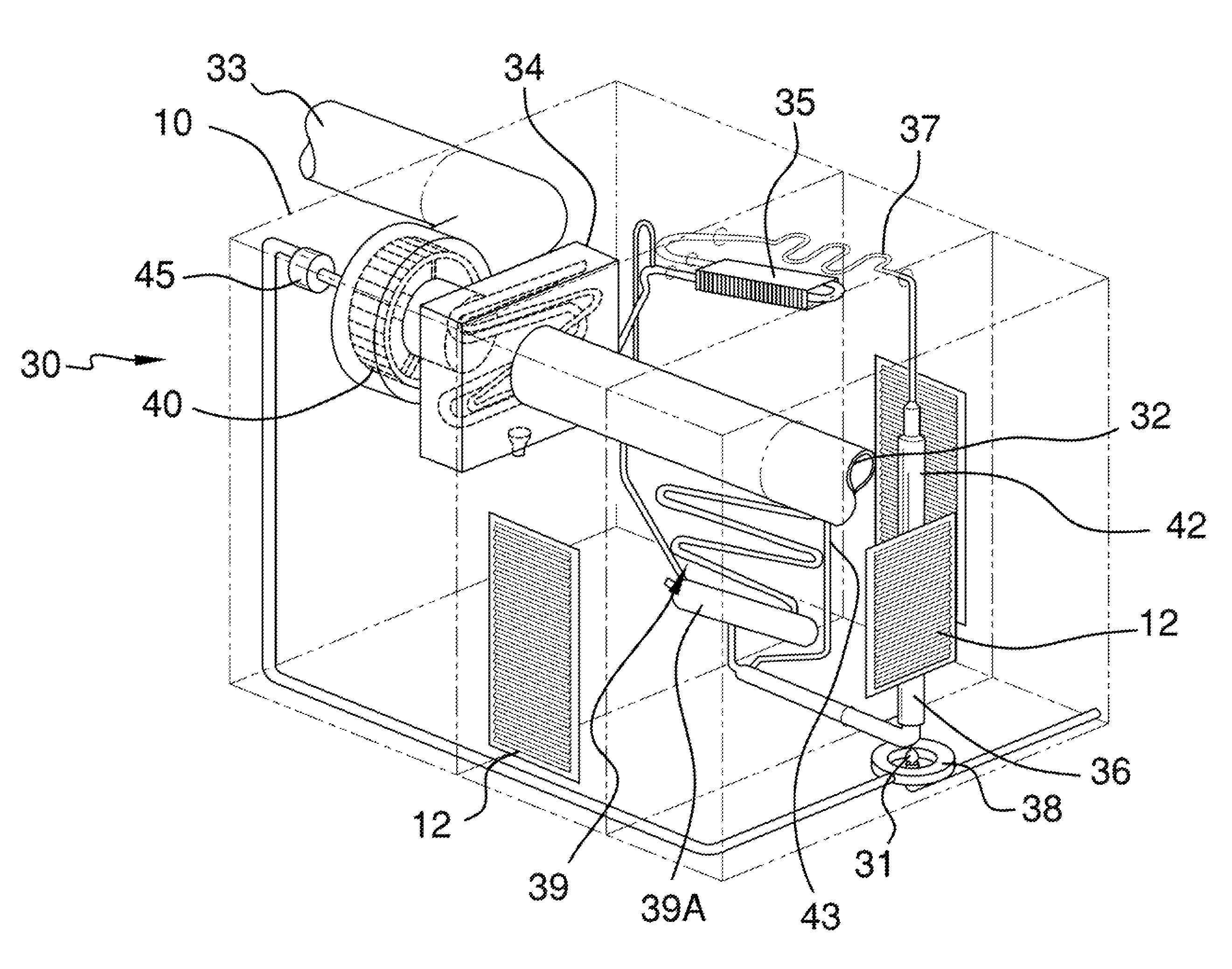
[0024]Referring to FIG. 3A, the invention 8 has located within the housing 10 is an absorption system 30. The absorption system 30 includes a burner 31, a return port 32, a supply port 33, an evaporator 34, a condenser 35, a central tube 36, a water separator 37, a thermoelectric power module 38, an absorber 39, an absorber vessel 39A, a fan 40, and a low voltage, high efficiency DC fan motor 45 (hereinafter fan motor).

[0025]It shall be noted that the central tube 36 consists of a boiler and a siphon pump (not depicted in detail). The heat generated by the burner 31, is introduced into the region designated as central tube 36, and that the actual piping contains along the bottom portion a boiler (not shown), and along the top portion a siphon pump (not shown). It is known to those skilled in the art how a boiler and siphon pump operates, and as such no discussion is warranted.

[0026]It shall be noted that the absorption system 30 may include a plurality of burners 31. However, in FIG...

second embodiment

[0042]Referring to FIG. 3B, the invention 8 contains a thermoelectric power generator 50. FIG. 4 provides for the electrical diagram should the thermoelectric power generator 50 be employed over the thermoelectric power module 38, or the battery supply (not shown) that is charged by either a solar array (not shown) or with an electrical line (not shown). It shall be noted that the thermoelectric power generator 50 includes both a heat exchanger 51 and a thermoelectric power generator module 52.

[0043]Referring to FIG. 4, the thermoelectric power generator module 52 could be mounted on the heat exchanger 51 that would be positioned near the burner 31.

[0044]Heat introduced by a burner flame 31 into the heat exchanger 51 is converted into electricity by the thermoelectric power generator module 52. The invention 8 may include an AC line voltage 53, if necessary a thermostat 54, an inverter 55, an electronic heater coil 56, and diodes 58. The diodes 58 control the pathway of electricity....

third embodiment

[0046]A variation of the invention 8 would provide for the inclusion of a thermoelectric power generator module 52 and heat exchanger 51 as depicted in FIG. 3B.


PUM


Abstract

The present invention relates to an outdoor portable cooling system for patios, campsites, and other related areas. The invention is primarily to be used as a portable cooling system, but may be adapted as a permanently affixed cooling system. The invention includes a housing that contains an absorption system that would be powered by a propane burner. Heat generated by the burning propane gas can be used to operate the fan motor via a module that produces electricity from heat or whereby the motor is powered by a battery supply. The battery supply may be recharged by a solar panel or by a standard electrical line.

Description

CROSS REFERENCES TO RELATED APPLICATIONSNot ApplicableSTATEMENT REGARDING FEDERALLY SPONSORED RESEARCHNot ApplicableREFERENCE TO APPENDIXNot ApplicableBACKGROUND OF THE INVENTION[0001]A. Field of the Invention[0002]The present invention relates to an outdoor portable cooling system for patios, campsites, and other related areas. Typically, portable cooling systems were limited to operating only in areas with an external source of electricity. This invention seeks to remedy this restraint by providing a method for cooling a localized outdoor area or enclosed area through the use of a propane or other flammable gas.[0003]B. Discussion of the Prior Art[0004]The Herweg Patent (U.S. Pat. No. 3,740,964) discloses a portable air conditioner comprising a cooling unit to be placed in a zone to be cooled, and a refrigerant condensing unit to be placed outside of the zone. However, this system is dependent on electrical power supply, as opposed to a portable air conditioner system that is powe...

Claims


Application Information

Patent Timeline
Patent Type & Authority Patents(United States)
IPC IPC(8): F25B15/00
CPCF24F1/04F25B15/10Y02B30/62Y02A30/27
Inventor HEATER, TIMWEBER, TIMHALL, SCOTTREED, CHUCKABLES, DAVIDCARPENTER, MIKE
Owner HEATER TIM
Why Eureka
Try Eureka