Mounting adapter for concrete surface processing tool

a technology for mounting adapters and concrete, which is applied in manufacturing tools, carpet cleaners, and ways. it can solve the problems of large investment in and ownership or lease of separate equipment, long time-consuming and laborious, and expensive equipment for concrete contractors

Inactive Publication Date: 2010-10-19
WAGMAN METAL PRODS
View PDF13 Cites 33 Cited by
  • Summary
  • Abstract
  • Description
  • Claims
  • Application Information

AI Technical Summary

Benefits of technology

[0018]It is, therefore, a primary object of the present invention to provide a mounting adapter for surface processing tools which allows their use on conventional power trowel machines having spider assembly arms.
[0019]It is another object of the present invention to provide a mounting adapter which allows advantage to be taken of the presence at a concrete floor construction site of high square footage capacity power trowel machines for surface processing purposes.
[0020]It is still another object of the present invention to provide a mounting adapter which allows the rapid, on-site substitution of surface processing tools on spider arms in place of the trowel blades used during concrete floor installation.
[0021]It is yet another object of the present invention to provide a mounting adapter for surface processing tools on spider assemblies which allows the surface processing tools to spin freely about their axes while the spider arms are rotatably driven in order to encourage more uniform wear of the tools and a longer useful life.
[0022]It is another object of the present invention to provide a mounting adapter which greatly increases the strength of the attachment between the mounting shank and the mounting bar and between the mounting bar and the spider arm.
[0027]said bearing means being rotatable relative to said shank means for rotatably mounting said surface processing tool, whereby said surface processing tool can spin freely about its axis.

Problems solved by technology

When it is appreciated that large warehouse floors may be hundreds of thousands of square feet, it can be seen that performing a finishing operation on large area floors using walk behind type brush machines will either take a very long time or require many operators and machines.
In addition, generally, concrete contractors do not have floor polishing machines on site and typically do not own such machines.
Therefore, where conventional floor polishing machines are used to surface finish concrete surfaces, concrete contractors have to invest in and own or lease separate, expensive pieces of equipment.

Method used


Image

  • Mounting adapter for concrete surface processing tool
  • Mounting adapter for concrete surface processing tool
  • Mounting adapter for concrete surface processing tool

Examples


second embodiment

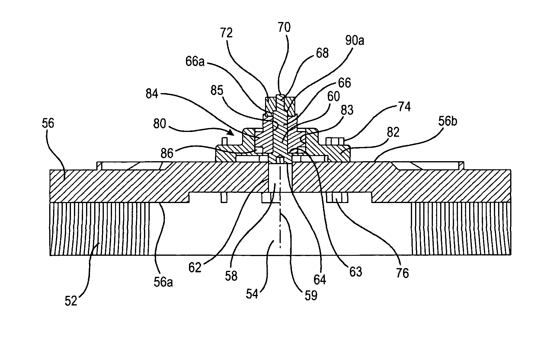
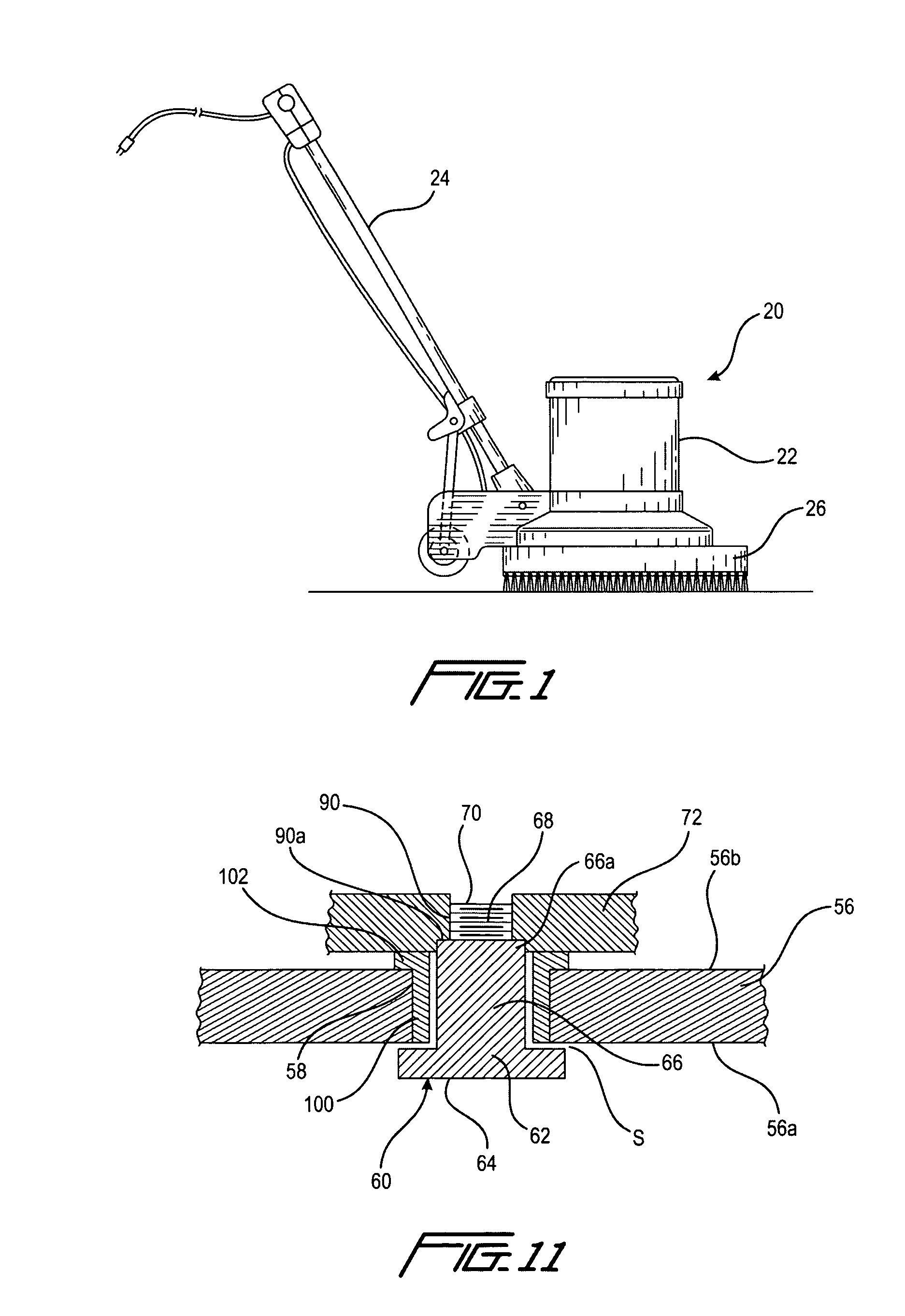
[0038]Referring to FIGS. 8-11 there is shown the mounting adapter of the present invention. Features common to each of the embodiments are designated by the same reference numerals. Circular brush assembly 50 includes a circular bristle brush 52 in the form of a ring having a hollow center 54 mounted to or with the bristles extending from the underside 56a of a brush cover plate 56, which may be flat or slightly convex. Cover plate 56 includes a central aperture 58 for receiving a mounting shank 60 therethrough. Shank 60 includes a head 62 at one end 64, a smooth surfaced, generally cylindrical shank portion 66 extending from head 62 to a point intermediate the ends of the shank 60 and a threaded portion 68 extending from the end of the smooth shank portion 64 to the end 70 of the shank opposite the shank head 62. A brush assembly 50 is mounted to one of the arms 32 of a spider assembly 30 by first mounting the brush assembly to a mounting means 72, such as an elongate mounting bar,...

first embodiment

[0041]As with the first embodiment, additional apertures 92 are provided in mounting bar 72 for attaching the brush assembly 50 to the rotor arms of the power trowel using at least two bolts, which extend through the rotor arms and are received in apertures 92. An advantage of the present mounting adapter is that, by virtue of mounting bar 72, it permits the brush assembly 50 be attached to the arms 32 of spider assembly 30 using multiple bolts to provide added strength and reduce wear at the area of greatest operational stress. In addition, inasmuch as the mounting adapter of the present invention will be used with spider assemblies of many different manufacturers, the mounting bar 72 serves as a readily interchangeable interface between the mounting adapter and the spider assembly and can be readily altered to suit the configuration and bolt hole locations of the spider assembly. It will be appreciated that the mounting means need not be a mounting bar, but can be any well known m...


PUM


Abstract

A mounting assembly for rotatably mounting a surface processing tool holder on at least one motor driven rotatable arm of a surface processing apparatus, such that the tool can spin freely as the arm is driven by the motor, includes an elongate shank having a smooth surfaced, cylindrical portion intermediate its ends adapted for positioning within an aperture in the tool holder with one threaded end portion projecting through the aperture for attachment to an elongate mounting bar adapted for attachment to the arm. A bearing supported by the tool body and surrounding the smooth surfaced portion of the shank is rotatable relative to the shank. The mounting bar includes a threaded aperture for receiving the threaded end portion of the shank and the threaded aperture includes a counterbore for receiving the end portion of the smooth surfaced shank portion which is adjacent the threaded end portion.

Description

CROSS-REFERENCE TO RELATED APPLICATIONS[0001]This is a non-provisional application based upon U.S. provisional applications Ser. No. 60 / 961,862, filed Jul. 25, 2007, now pending, and Ser. No. 61 / 065,954, filed Feb. 16, 2008, now pending.FIELD OF THE INVENTION[0002]The present invention relates to surface processing machines for mounting surface processing tools and, more particularly, to mounting means for rotatably mounting circular brushes on the arms of motor driven spider arm assemblies of such machines.BACKGROUND OF THE INVENTION[0003]Typically, when large area concrete floors are installed, they may be surface finished, e.g., texturized, cleaned, prepared for subsequent application of a penetrating sealer or other substance, using a surface processing machine, such as conventional walk behind floor polishing-type machines 20 comprising a gas or electric engine 22, a handle 24 for machine control and steering and a circular rotating brush 26 driven by engine 22, as shown in FIG...

Claims


Application Information

Patent Timeline
Patent Type & Authority Patents(United States)
IPC IPC(8): E01C19/22A47L11/00B24B41/00
CPCB24B7/186B24B45/006E04F21/24E04F21/247E04F21/248
Inventor SNYDER, JEFFREY L.MILLER, BRETT L.
Owner WAGMAN METAL PRODS
Why Eureka
Try Eureka