

Capacitor and method for manufacturing same
a technology of capacitors and capacitors, applied in the field of capacitors, can solve the problems of electrolyte leakage from metal casings, and achieve the effect of high reliability
- Summary
- Abstract
- Description
- Claims
- Application Information
AI Technical Summary
Benefits of technology
Problems solved by technology
Method used
Image

Examples
exemplary embodiment 1
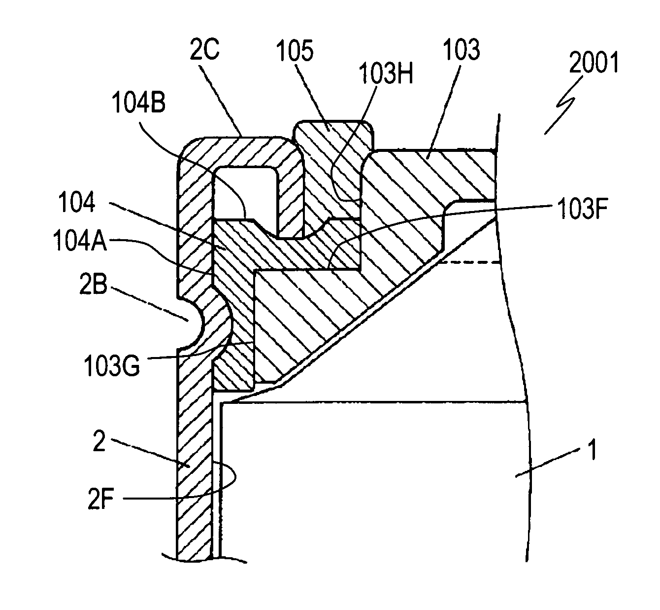
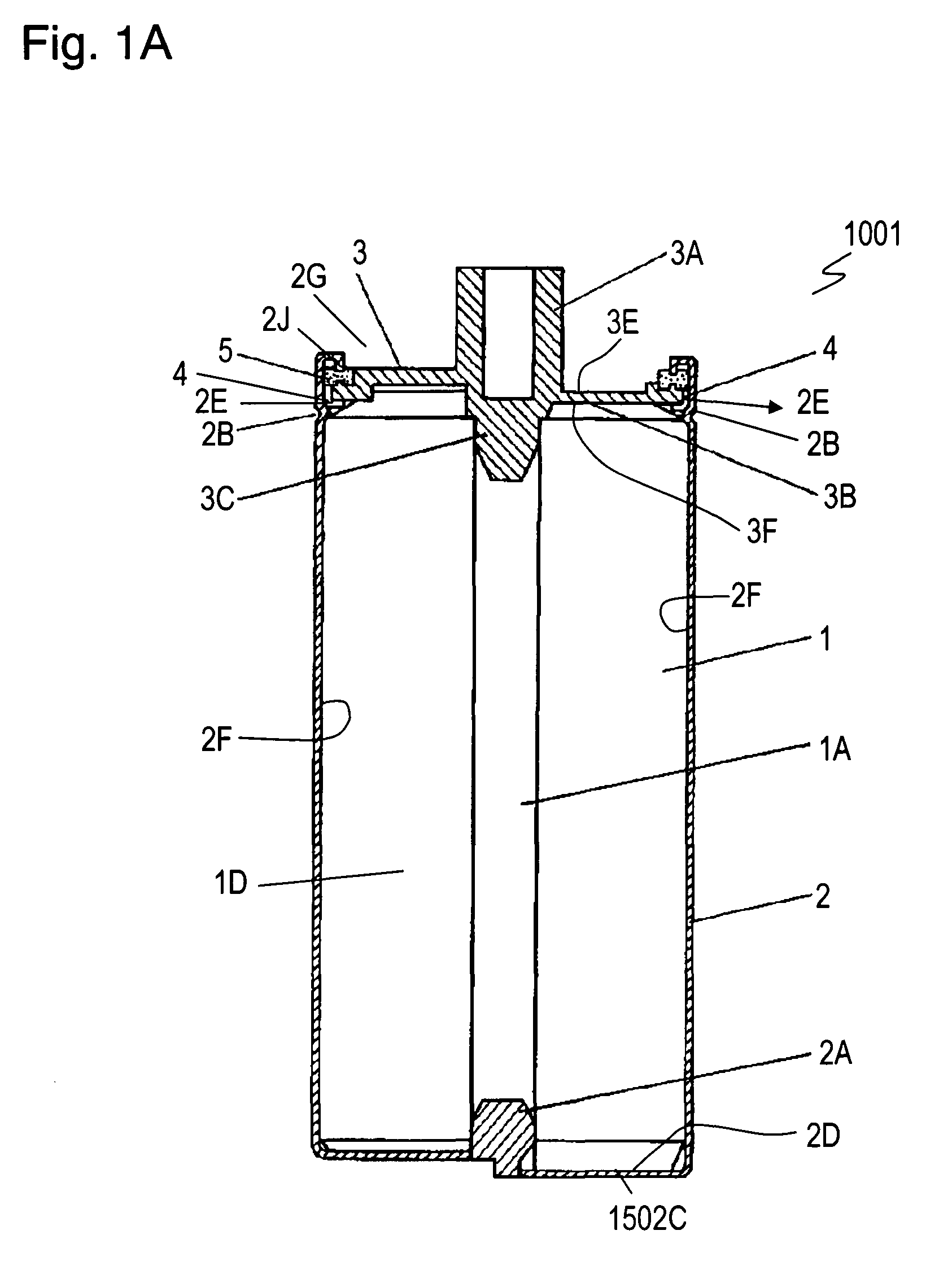
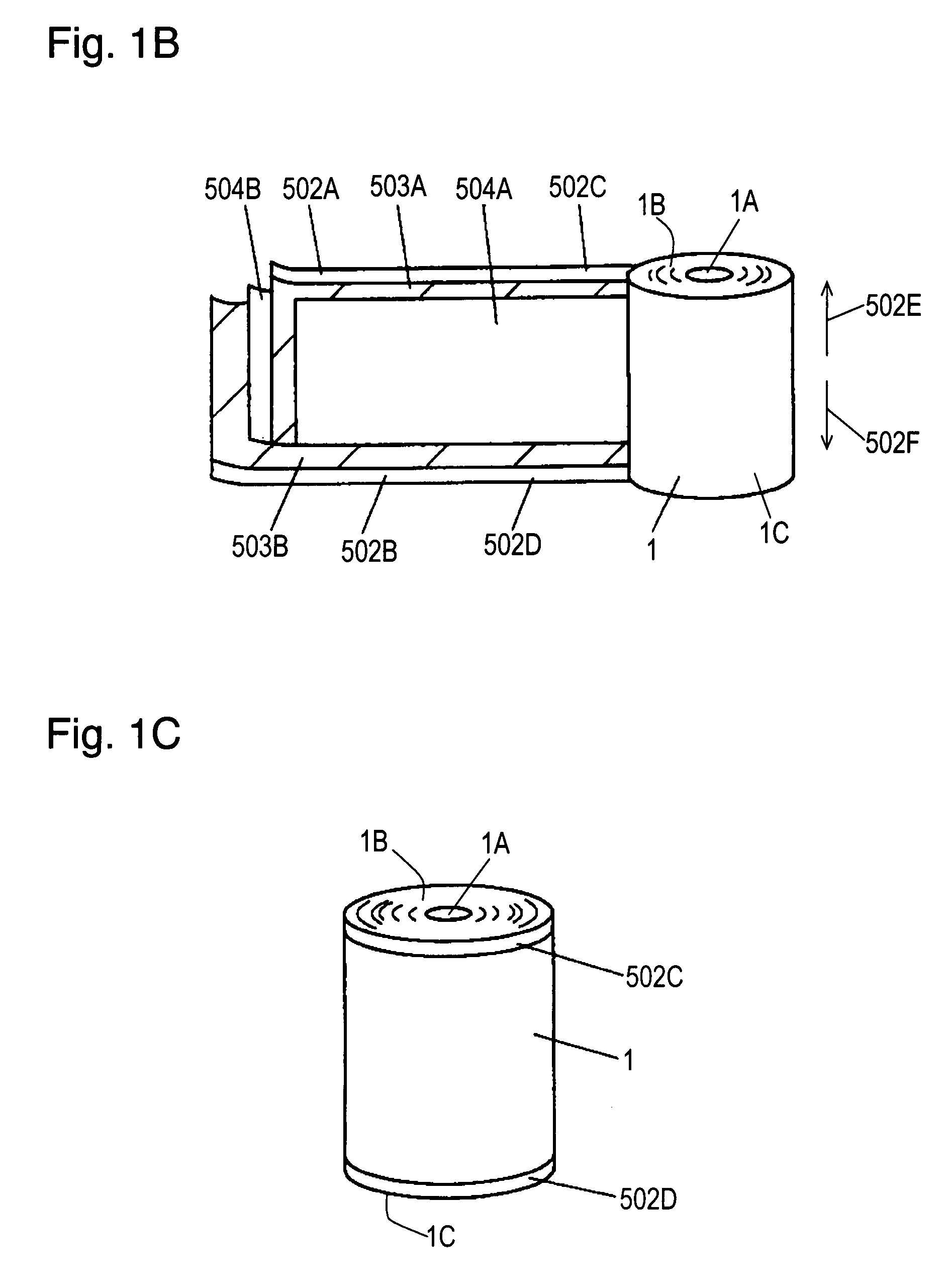
[0149]FIG. 1A is a cross sectional view of a capacitor 1001 according to Exemplary Embodiment 1 of the present invention. FIG. 1B is an exploded perspective view of a capacitor element 1 of the capacitor 1001. FIG. 1C is a perspective view of the capacitor element 1. FIGS. 2A and 2B are cross sectional views of essential parts of the capacitor 1001.
[0150]The capacitor element 1 includes a collector 502B made of aluminum foil, a polarized layer 503B provided on the collector 502B, an insulating separator 504B provided on the polarized layer 503B, a collector 502A made of aluminum foil, a polarized layer 503A provided on the collector 502A, and an insulating separator 504A provided on the polarized layer 503A. The polarized layer 503B is made of mixture of activated carbon, binder, and conductive material. The collectors 502A and 502B, the polarized layers 503A and 503B, and the separators 504A and 504B are rolled to form the capacitor element 1 having a hollow 1A provided in the cent...
exemplary embodiment 2
[0164]FIG. 4 is a top view of a sealing rubber 5 of a capacitor 1002 according to Exemplary Embodiment 2 of the present invention. FIG. 5A is a cross sectional view of an essential part of the capacitor 1002 before a metal case 2 is subjected to the curling process, i.e., before the metal case 2 is sealed. FIG. 5B is a cross sectional view of the essential part of the capacitor 1002 after the metal case 2 is sealed. The same components as those of the capacitor 1001 according to Embodiment 1 shown in FIGS. 1A to 2B are denoted by the same reference numerals, and their description will be omitted.
[0165]The sealing rubber 5 having a ring shape has an inner diameter 5C and an outer diameter 5D. The sealing rubber 5 may be made of peroxide vulcanized rubber or resin vulcanized rubber while the rubber 5 according to Embodiment 1 is made from butyl rubber (isobutylene isoprene rubber).
[0166]As shown in FIG. 5A, the metal case 2 has an inner diameter 2D. An outer edge surface 3K of the ter...
exemplary embodiment 3
[0171]FIG. 7 is a cross sectional view of a capacitor 1004 according to Exemplary Embodiment 3 of the present invention. A positive lead terminal electrode 7A and a negative lead terminal electrode 7B extend from a capacitor element 6. The capacitor element 6 is accommodated together with an electrolyte 6A in a metal case 9 having a bottom 9B and a sealing rubber 8. The metal case 9 has a narrowed portion 9A at which a diameter of the metal case 9 is reduced locally. The metal case 9 has a diameter D2 at an opening 9C and a diameter D3 at the narrowed portion 9A. The sealing rubber 8 has through-holes 8A and 8B provided therein through which the positive lead terminal electrode 7A and the negative lead terminal electrode 7B are inserted, respectively.
[0172]The resultant measurements of the air tightness test shown in FIG. 3 can be applied to the capacitor 1004, similarly to the capacitor 1001 according to Embodiment 1 The sealing rubber 8 is compressed at the narrowed portion 9A, th...
PUM
| Property | Measurement | Unit |
|---|---|---|
| thickness | aaaaa | aaaaa |
| breaking elongation rate | aaaaa | aaaaa |
| Young's modulus | aaaaa | aaaaa |
Abstract
Description
Claims
Application Information