
Laser-triggered plasma apparatus for atomic emission spectroscopy

a plasma apparatus and atomic emission technology, applied in the direction of optical radiation measurement, instruments, spectrometry/spectrophotometry/monochromators, etc., can solve the problems of difficult control, limited application of ed techniques, and difficult to achieve high stability of sensed optical signals

Inactive Publication Date: 2010-10-26
THERMO NITON ANALYZERS
View PDF7 Cites 40 Cited by
  • Summary
  • Abstract
  • Description
  • Claims
  • Application Information

AI Technical Summary

Benefits of technology

"The present invention provides a method and apparatus for analyzing the composition of a sample using an optical spectroscopic instrument. The method involves creating a plasma at a controlled location in a proximity of the sample by applying a first electromagnetic field and a second electromagnetic field in a pulse of energy per unit area less than the threshold ablation energy of the sample. The plasma is then detected by dispersing the emission in a spectrometer or using a hand-holdable apparatus with a laser, optical element, electrodes, and spectrometer. The apparatus may also have a polarization control element and a bias supply for applying an electric field across the controlled location in the proximity of the sample prior to providing successive pulses of optical energy. The technical effects of the invention include improved accuracy and precision in analyzing sample composition and the ability to detect and analyze small amounts of sample."

Problems solved by technology

Electrical discharge (ED) techniques are widely used in some of the most precise analytical instruments built today, but application of ED techniques is limited to samples that are conductive.
On the other hand, the precise location of plasma formation by ED techniques is difficult to control, making it, in turn, difficult to achieve high stability of the sensed optical signals.
Indeed, erratic motion of the plasma location across the sample surface during the course of a measurement adds noise to the sensed optical signal.
Moreover, the geometrical requirements, both with regard to sample proximity to the electrode and axial centering, limit the solid angle from which spectral signal may be obtained.
LIBS equipment is expensive and far more complex than electrical discharge systems.
Multiple laser pulses, delivered in rapid succession may require the use of multiple lasers, dramatically increasing the cost and complexity of such systems.

Method used


Image

  • Laser-triggered plasma apparatus for atomic emission spectroscopy
  • Laser-triggered plasma apparatus for atomic emission spectroscopy
  • Laser-triggered plasma apparatus for atomic emission spectroscopy

Examples


Embodiment Construction

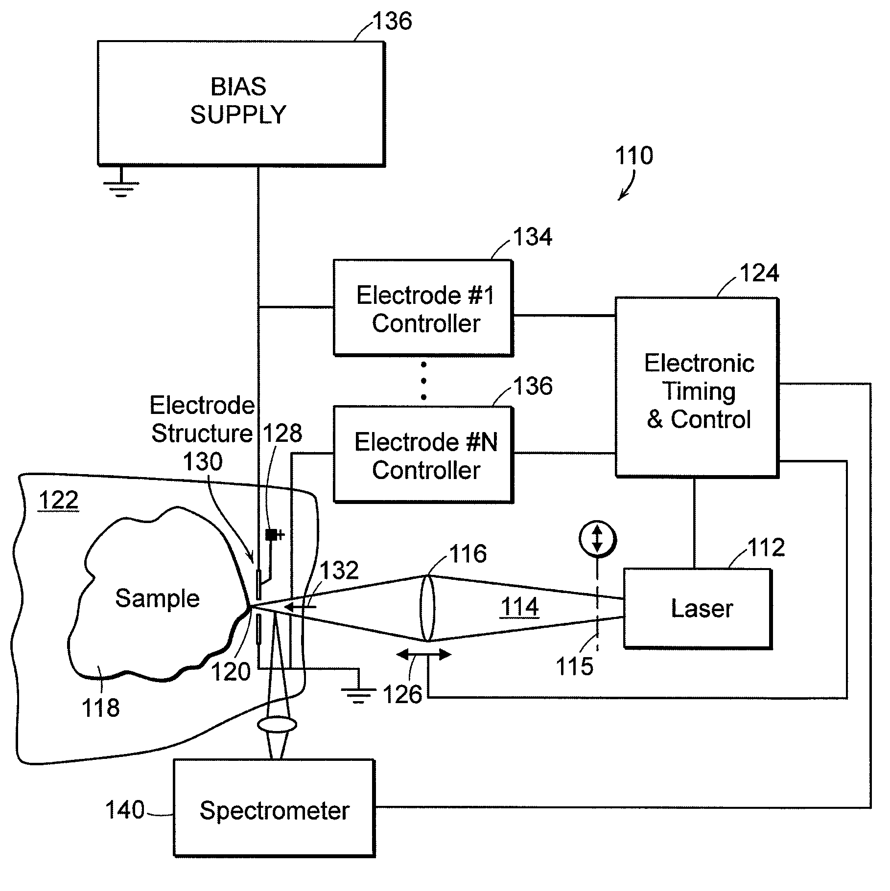
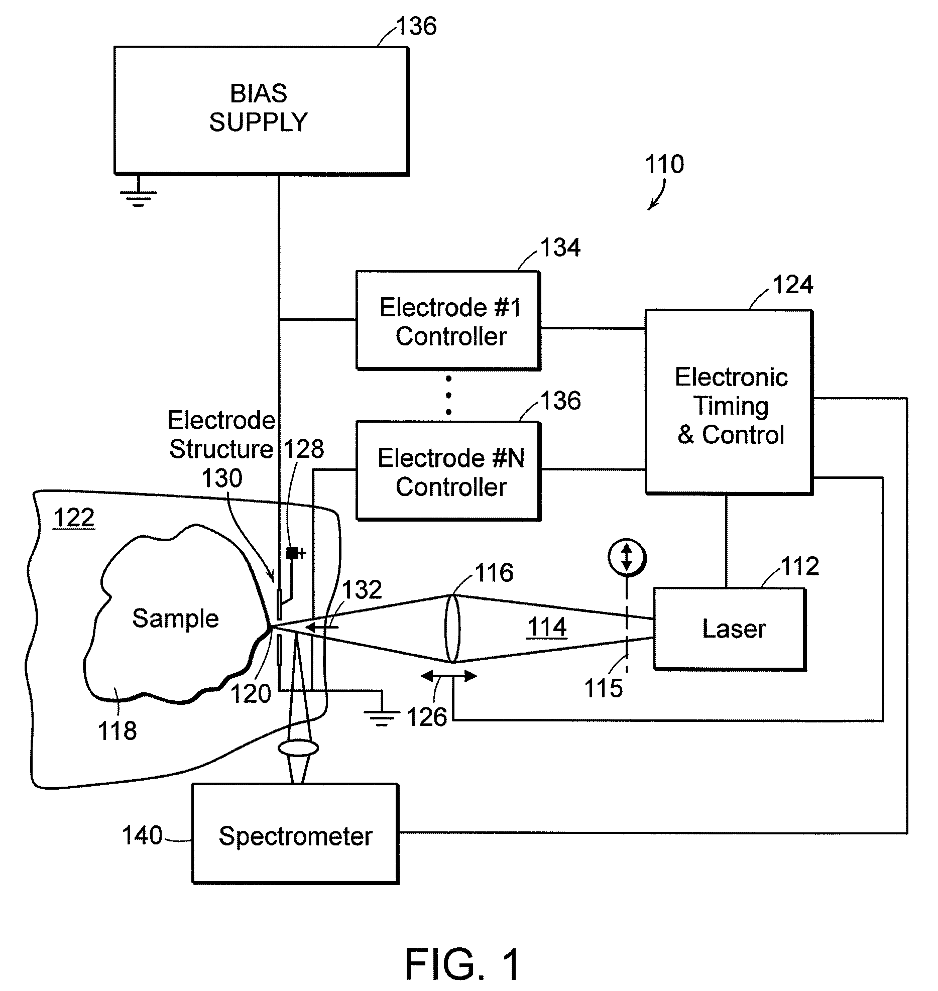
[0036]Preferred embodiments of the invention described herein are directed to the use of multiple energy sources to excite material for subsequent analysis of optical emission, obtaining advantages of synergy and eliminating some of the source-specific drawbacks. In accordance with certain of the preferred embodiments of the present invention, multiple energy sources are employed within a single hand-held or portable optical emission spectroscopy (OES) device in order to create a suitably energetic and controlled plasma for spectroscopic characterization.

[0037]Definitions: As used herein and in any appended claims, energy sources are distinct when their energy spectra are non-identical, whether or not their respective applications overlap in time. Moreover, the energy spectrum of one of the energy sources may include a static field, which may be characterized as a “DC” field, whether or not current is actually flowing, and without regard to the duration of time during which the stat...


PUM


Abstract

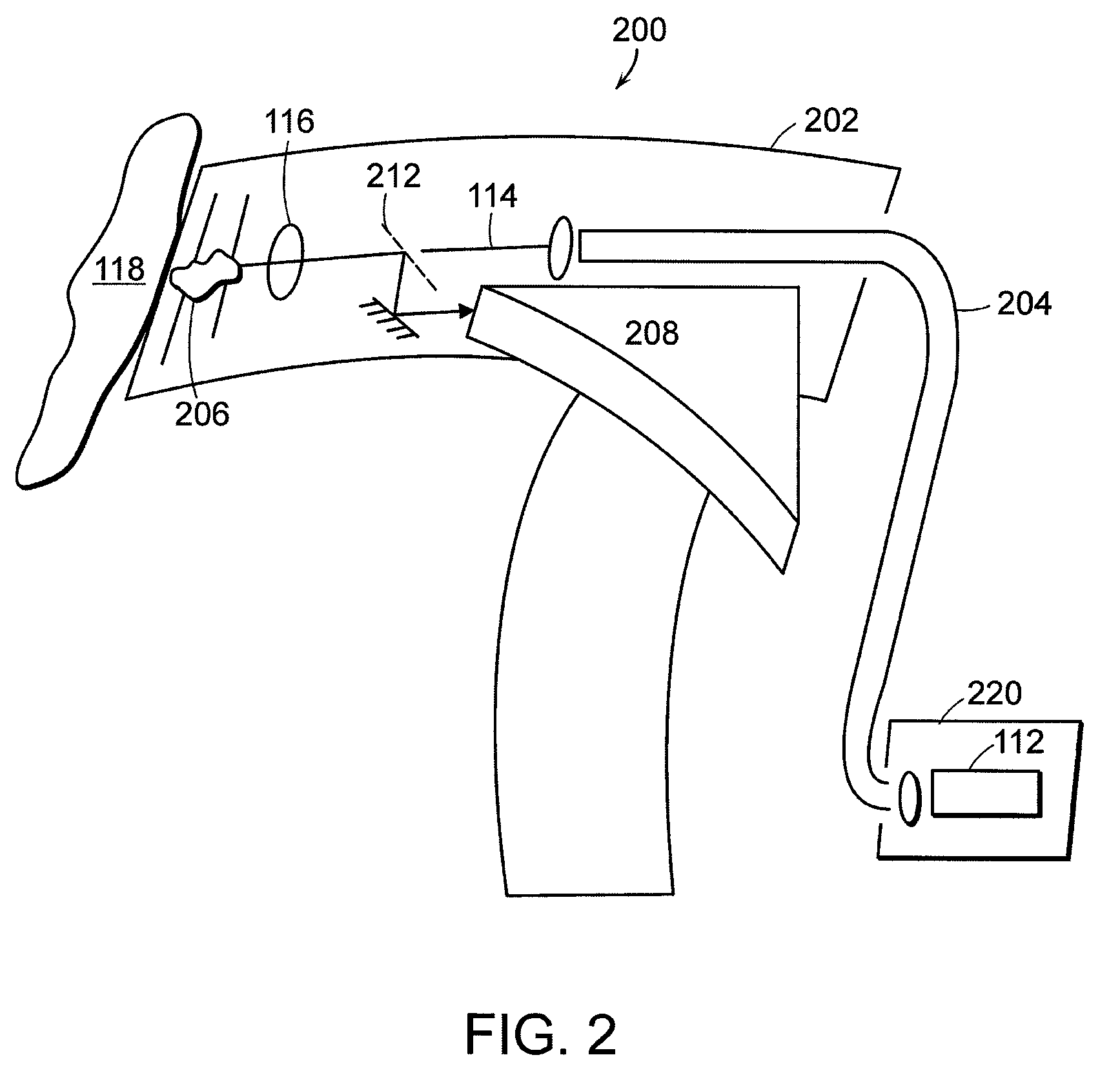
Multiple energy sources, such as a laser and electrical current, are employed, in close coordination, spatially and temporally, to clean a sample, vaporize its material and excite vapor atoms for the purpose of atomic emission spectroscopy. These methods permit better monitoring and control of the individual processes in real time, lead to higher consistency and higher quality optical emission spectra, and enhance the measurements of non-conducting solids, liquids and gases. Additionally, a portable instrument is provided with both laser source and spectrometer optically coupled to a hand-holdable unit.

Description

[0001]The present application claims the priority of U.S. Provisional Patent Application Ser. No. 60 / 925,383, filed Apr. 20, 2007, which is incorporated herein by reference in its entirety.TECHNICAL FIELD[0002]The present invention relates to methods and devices for performing spectroscopic measurements of samples vaporized and excited through a combination of laser and spark excitation mechanisms, provided, in some embodiments, within a self-contained, hand-held instrument.BACKGROUND ART[0003]The field of atomic emission spectroscopy was developed at the time of Johann Balmer, Johannes Rydberg, Friedrich Paschen, and their contemporaries, during the late 1800s, when flame was used as an excitation source. Atomic emission spectroscopy is now applied to almost every scientific discipline including physics, astronomy, chemistry, biochemistry, medicine, forestry and agriculture, geology and mining, forensic science, environmental protection, metallurgy and metal production, etc. Innova...

Claims


Application Information

Patent Timeline
Patent Type & Authority Patents(United States)
IPC IPC(8): G01J3/30
CPCG01J3/02G01J3/0272G01J3/443G01N21/67G01N21/718
Inventor DILLON, ROBERTGRODZINS, LEEMELIKIAN, STEPHANIE
Owner THERMO NITON ANALYZERS
Learn More