Optical pickup device and optical disk device

a pickup device and optical disk technology, applied in the direction of mountings, instruments, data recording, etc., can solve the problems of increasing the amount of spherical aberration caused by varying wavelengths, oscillation wavelength, and increasing so as to reduce the amount of spherical aberration, increase the yield of light sources, and extend the tolerance range of differences

Active Publication Date: 2010-10-26
SONY CORP
View PDF2 Cites 4 Cited by
  • Summary
  • Abstract
  • Description
  • Claims
  • Application Information

AI Technical Summary

Benefits of technology

[0011]It is thus desirable to provide, for use in a device of performing recording and / or reproduction of information with respect to a high-density-recording optical disk, an optical pickup device and an optical disk device that can extend the tolerance range of a variation of an oscillation wavelength in a light source, and sufficiently reduce any aberration.
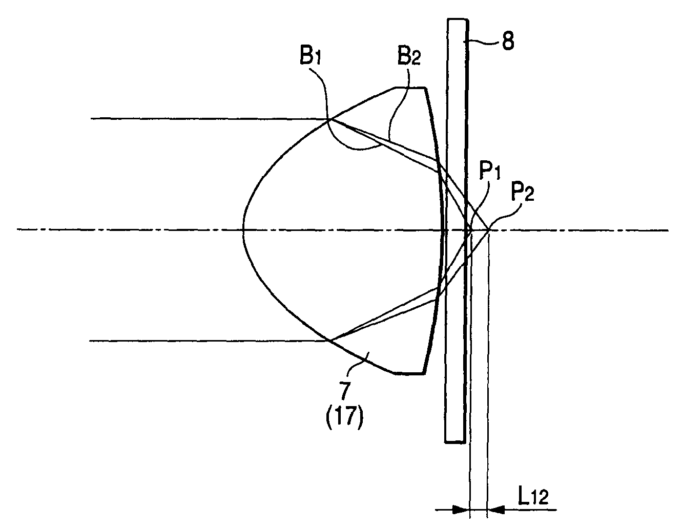
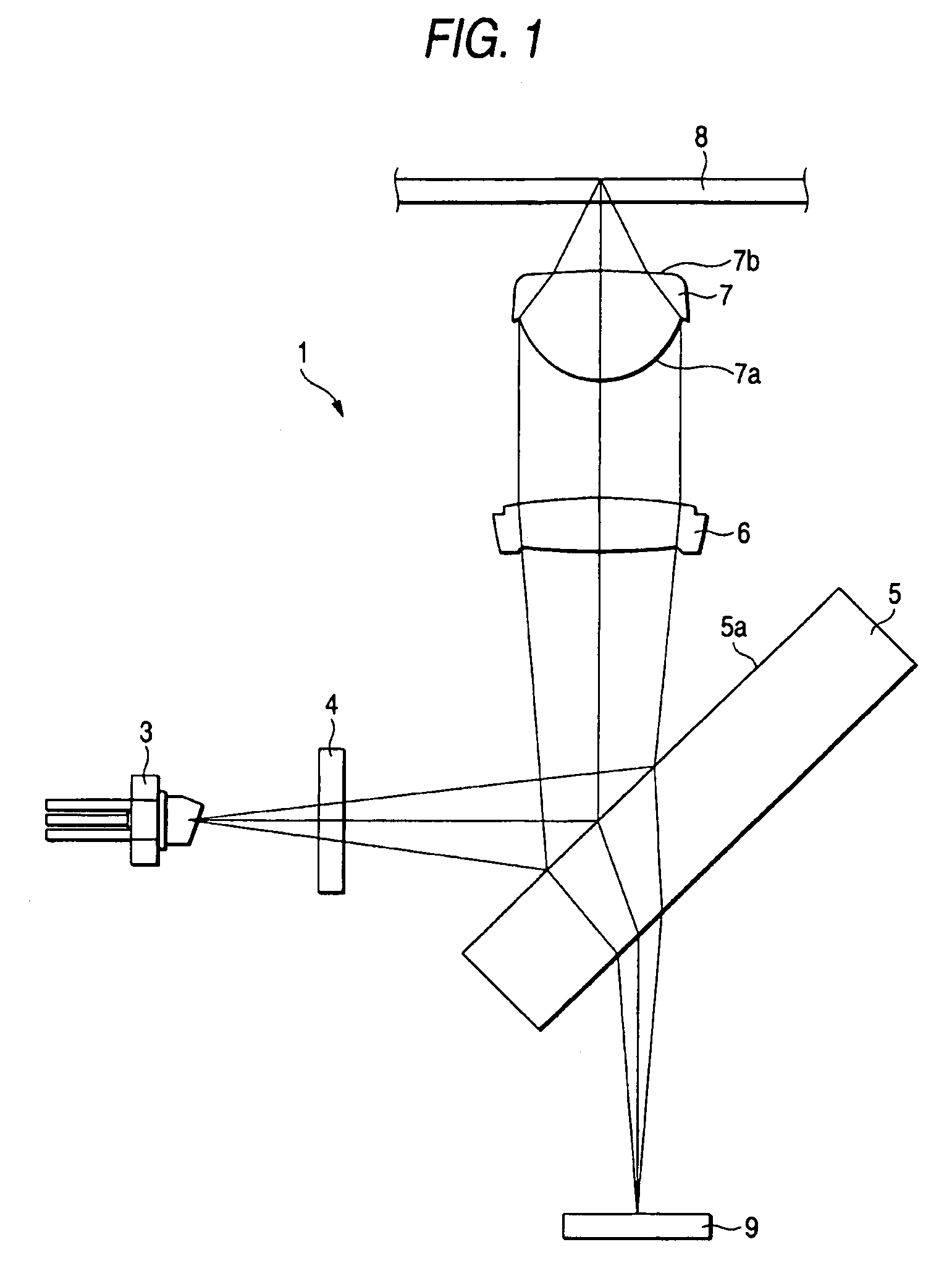
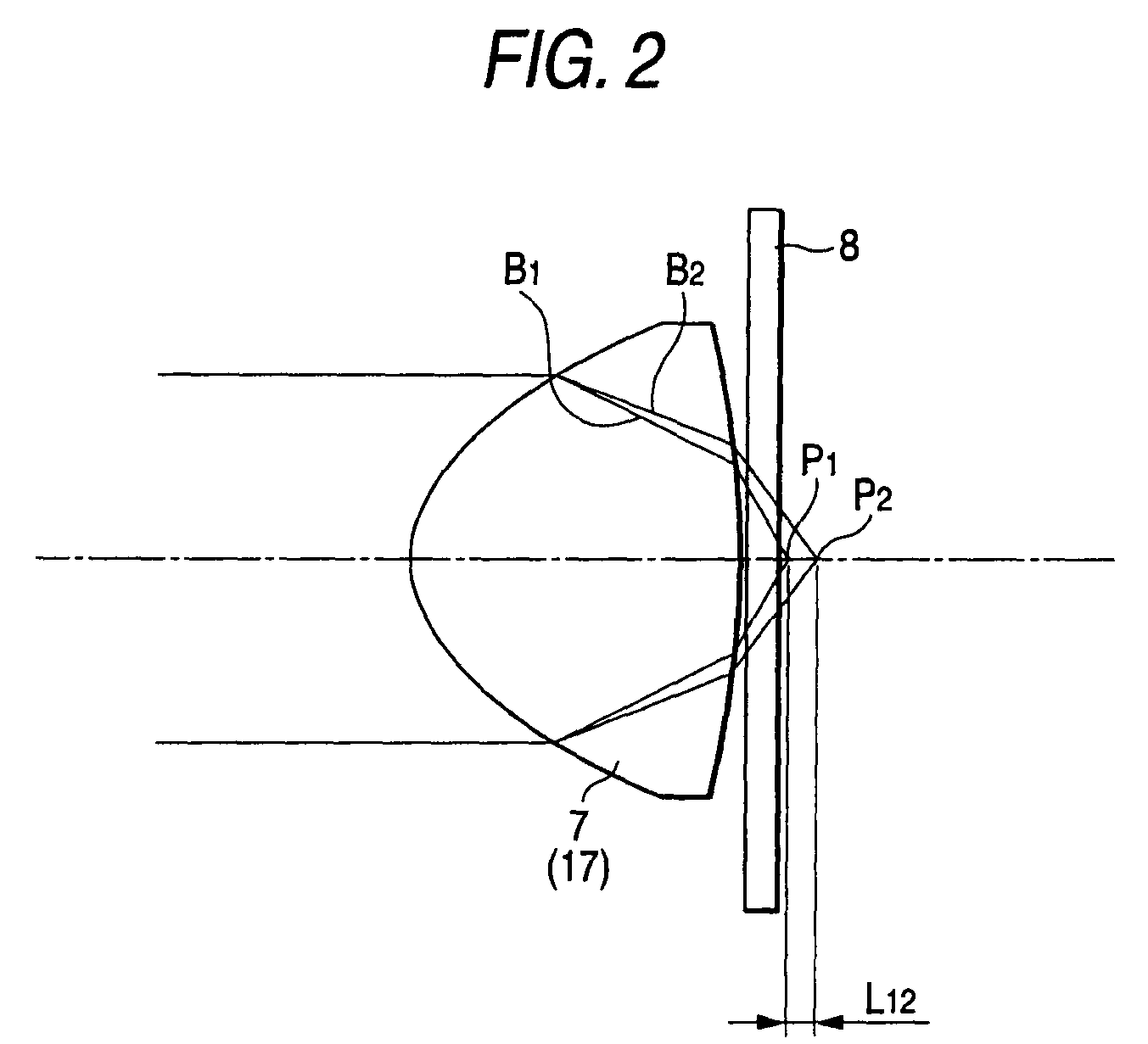
[0012]According to a first embodiment of the present invention, there is provided an optical pickup device, including: a light source that emits a light beam of a predetermined wavelength of about 405 nm; an objective lens being aplastic lens provided with, on at least one surface, diffraction means of a zone diffractive structure suppressing generation of aberration to be caused by a temperature change, and has a numerical aperture of 0.82 or larger for gathering the light beam emitted from the light source with respect to an optical disk; and a collimator lens disposed between the light source and the objective lens, and derives a substantially-collimated light by converting an angle of divergence of the light beam emitted from the light source. In the optical pickup device, the objective lens is formed to satisfy equation (1), where ΔSA3T is an amount of change of third-order spherical aberration to be generated in the objective lens in response to a temperature change ΔT (° C.) in a range from −10° C. to 75° C., and ΔSA3λ is an amount of change of third-order spherical aberration to be generated in the objective lens in response to a wavelength change Δλ (nm) within a range of ±5 nm observed in the light beam emitted from the light source, equation (3) is satisfied when a length of an optical path increased by the diffractive structure of the diffraction means is represented by an optical-path difference function φ(h) calculated by equation (2), where h (mm) is a height from an optical axis, Cn is an nth-order coefficient of an optical-path difference, and λ (nm) is a wavelength of an incoming light beam, equation (4) is satisfied, where ΔSA3 is an amount of change of third-order axial spherical aberration to be generated in the objective lens in response to the wavelength change Δλ (nm), and ΔSA5 is an amount of change of fifth-order axial spherical aberration, and with the objective lens, the generation of the spherical aberration to be caused by the temperature change can be suppressed, and when the light beam emitted from the light source is changed in wavelength, the generation of the spherical aberration can be suppressed by moving the collimator lens.(ΔSA3T / ΔT)×(ΔSA3λ / Δλ)<0  (1)φ(h)=(C2×h2+C4×h4+C6×h6+C8×h8+C10×h10+ . . . )×λ / 106 (mm)  (2)C2×C10>0  (3)ΔSA3×ΔSA5>0  (4)
[0015]According to a second embodiment of the present invention, there is provided an optical disk device, including, an optical pickup device provided with: a light source that emits a light beam of a predetermined wavelength of about 405 nm; an objective lens being aplastic lens provided with, on at least one surface, diffraction means of a zone diffractive structure suppressing generation of aberration to be caused by a temperature change, and has a numerical aperture of 0.82 or larger for gathering the light beam emitted from the light source with respect to an optical disk; and a collimator lens disposed between the light source and the objective lens, and derives a substantially-collimated light by converting an angle of divergence of the light beam emitted from the light source, and performing recording and / or reproduction of an information signal with respect to the optical disk by the optical pickup device. In the optical disk device, the objective lens is formed to satisfy equation (7), where ΔSA3T is an amount of change of third-order spherical aberration to be generated in the objective lens in response to a temperature change ΔT (° C.) in a range from −10° C. to 75° C., and ΔSA3λ is an amount of change of third-order spherical aberration to be generated in the objective lens in response to a wavelength change Δλ (nm) within a range of ±5 nm observed in the light beam emitted from the light source, equation (9) is satisfied when a length of an optical path increased by the diffractive structure of the diffraction means is represented by an optical-path difference function φ(h) calculated by equation (8), where h (mm) is a height from an optical axis, Cn is an nth-order coefficient of an optical-path difference, and λ (nm) is a wavelength of an incoming light beam, equation (10) is satisfied, where ΔSA3 is an amount of change of third-order axial spherical aberration to be generated in the objective lens in response to the wavelength change Δλ (nm), and ΔSA5 is an amount of change of fifth-order axial spherical aberration, and with the objective lens, the generation of the spherical aberration to be caused by the temperature change can be suppressed, and when the light beam emitted from the light source is changed in wavelength, the generation of the spherical aberration can be suppressed by moving the collimator lens.(ΔSA3T / ΔT)×(ΔSA3λ / Δλ)<0  (7)φ(h)=(C2×h2+C4×h4+C6×h6+C8×h8+C10×h10+ . . . )×λ / 106 (mm)  (8)C2×C10>0  (9)ΔSA3×ΔSA5>0  (10)
[0016]According to a third embodiment of the present invention, there is provided an optical pickup device, including: a light source that emits a light beam of a predetermined wavelength of about 405 nm; an objective lens being a plastic lens provided with, on at least one surface, diffraction means of a zone diffractive structure suppressing generation of aberration to be caused by a temperature change, and has a numerical aperture of 0.82 or larger for gathering the light beam emitted from the light source with respect to an optical disk; and a collimator lens disposed between the light source and the objective lens, and derives a substantially-collimated light by converting an angle of divergence of the light beam emitted from the light source. In the optical pickup device, the objective lens is formed to satisfy equation (11), where ΔSA3T is an amount of change of third-order spherical aberration to be generated in the objective lens in response to a temperature change ΔT (° C.) in a range from −10° C. to 75° C., and ΔSA3% is an amount of change of third-order spherical aberration to be generated in the objective lens in response to a wavelength change Δλ (nm) within a range of ±5 nm observed in the light beam emitted from the light source, equation (13) is satisfied when a length of an optical path increased by the diffractive structure of the diffraction means is represented by an optical-path difference function φ(h) calculated by equation (12), where h (mm) is a height from an optical axis, Cn is an nth-order coefficient of an optical-path difference, and λ (nm) is a wavelength of an incoming light beam, equation (14) is satisfied, where ΔSA3 is an amount of change of third-order axial spherical aberration to be generated in the objective lens in response to the wavelength change Δλ (nm), and ΔSA5 is an amount of change of fifth-order axial spherical aberration, and with the objective lens, the generation of the spherical aberration to be caused by the temperature change can be suppressed, and when the light beam emitted from the light source is changed in wavelength, the generation of the spherical aberration can be suppressed by moving the collimator lens.(ΔSA3T / ΔT)×(ΔSA3λ / Δλ)<0  (11)φ(h)=(C2×h2+C4×h4+C6×h6+C8×h8+C10×h10+ . . . )×λ / 106 (mm)  (12)C4×C10>0  (13)ΔSA3×ΔSA5>0  (14)
[0018]According to a fourth embodiment of the present invention, there is provided an optical disk device, including, an optical pickup device provided with: a light source that emits a light beam of a predetermined wavelength of about 405 nm; an objective lens being a plastic lens provided with, on at least one surface, diffraction means of a zone diffractive structure suppressing generation of aberration to be caused by a temperature change, and has a numerical aperture of 0.82 or larger for gathering the light beam emitted from the light source with respect to an optical disk; and a collimator lens disposed between the light source and the objective lens, and derives a substantially-collimated light by converting an angle of divergence of the light beam emitted from the light source, and performing recording and / or reproduction of an information signal with respect to the optical disk by the optical pickup device. In the optical disk device, the objective lens is formed to satisfy equation (16), where ΔSA3T is an amount of change of third-order spherical aberration to be generated in the objective lens in response to a temperature change ΔT (° C.) in a range from −10° C. to 75° C., and ΔSA3λ is an amount of change of third-order spherical aberration to be generated in the objective lens in response to a wavelength change Δλ (nm) within a range of ±5 nm observed in the light beam emitted from the light source, equation (18) is satisfied when a length of an optical path increased by the diffractive structure of the diffraction means is represented by an optical-path difference function φ(h) calculated by equation (17), where h (mm) is a height from an optical axis, Cn is an nth-order coefficient of an optical-path difference, and λ (nm) is a wavelength of an incoming light beam, equation (19) is satisfied, where ΔSA3 is an amount of change of third-order axial spherical aberration to be generated in the objective lens in response to the wavelength change Δλ (nm), and ΔSA5 is an amount of change of fifth-order axial spherical aberration, and with the objective lens, the generation of the spherical aberration to be caused by the temperature change can be suppressed, and when the light beam emitted from the light source is changed in wavelength, the generation of the spherical aberration can be suppressed by moving the collimator lens.(ΔSA3T / ΔT)×(ΔSA3λ / Δλ)<0  (16)φ(h)=(C2×h2+C4×h4+C6×h6+C8×h8+C10×h10+ . . . )× / 106(mm)  (17)C4×C10>0  (18)ΔSA3×ΔSA5>0  (19)
[0019]According to the embodiments of the invention, even when the oscillation wavelength shows a difference from the design wavelength due to manufacturing deviations or others occurred to a light source, an objective lens for use is so configured that an amount of change of third-order axial spherical aberration to be caused therein due to some wavelength change has a fixed relationship with an amount of change of fifth-order axial spherical aberration. This accordingly enables to correct and reduce the spherical aberration through adjustment of an optical system, extend the tolerance range of a difference from the design wavelength for the oscillation wavelength in the light source, increase the yield of the light source, and reduce the cost.

Problems solved by technology

The issue here is that, in an optical system of an optical pickup device for use with a so-called high-density-recording optical disk with a numerical aperture of 0.82 or larger, and the wavelength in use is of about 400 nm, i.e., short wavelength, even with a design wavelength of suppressing any axial spherical aberration, there is a problem that any variation of an oscillation wavelength caused due to manufacturing deviations or others in a semiconductor laser generates spherical aberration of an amount not permissive.
There is another problem that, when the optical system includes any component of diffractive structure, the spherical aberration to be caused due to the varying wavelength is increased in amount.
This resultantly reduces the yield of the semiconductor laser, thereby preventing the reduction of the cost.

Method used


Image

  • Optical pickup device and optical disk device
  • Optical pickup device and optical disk device
  • Optical pickup device and optical disk device

Examples


example 6

[0333]In the objective lens of Example 6, the reference characters f, n, d, and NA are as below.

[0334]f: 1.41 [mm]

[0335]n: 1.525

[0336]d: 1.93 [mm]

[0337]NA: 0.85

[0338]The reference characters R, K, and Ai representing the shape of the first surface on the light-entering side of the objective lens of Example 6 are as below. The nth-order coefficient Cn of an optical-path difference determining the length of increase φ (h) of the optical path by the zone diffractive structure provided to the first surface is as below.

[0339]Shape of First Surface

[0340]R: 0.921 [mm]

[0341]K: −0.662

[0342]A4: 1.108×10⁻²

[0343]A6: 2.098×10⁻²

[0344]A8: −2.414×10⁻²

[0345]A10: 1.585×10⁻²

[0346]A12: −4.195×10⁻³

[0347]A14: −3.362×10⁻³

[0348]A16: −3.060×10⁻³

[0349]A18: 8.197×10⁻³

[0350]A20: −3.879×10⁻³

[0351]C2: 17.55

[0352]C4: −30.03

[0353]C6: 21.63

[0354]C8: −28.00

[0355]C10: 5.79

[0356]The reference characters R, K, and Ai representing the shape of the second surface on the light-exiting side of the objective lens o...

example 1

[0426]In the objective lens of Example 1, the reference characters are as described above, i.e., f, n, d, and NA, R, K, and Ai indicating the shape of the first surface on the light-entering side, Cn indicating the nth-order coefficient of an optical path difference determining the length increase φ (h) for the optical path of the diffractive configuration provided to the first surface, and R, K, and Ai indicating the shape of the second surface on the light-exiting side.

[0427]In such an objective lens of Example 1, as a result of some wavelength change, any change observed between SA3 being the third-order spherical aberration and SA5 being the fifth-order spherical aberration is derived as shown in FIG. 6. In such an objective lens of the first example, the third-order spherical aberration on the axis is −0.2 mλrms, and the fifth-order spherical aberration is 0.4 mλrms, which are both suppressed to be sufficiently small.

[0428]The change of third-order spherical aberration with res...

example 2

[0433]In the objective lens of Example 2, the reference characters are as described above, i.e., f, n, d, and NA, R, K, and Ai indicating the shape of the first surface on the light-entering side, Cn indicating the nth-order coefficient of an optical path difference determining the length increase φ (h) for the optical path of the diffractive configuration provided to the first surface, and R, K, and Ai indicating the shape of the second surface on the light-exiting side.

[0434]In such an objective lens of Example 2, as a result of some wavelength change, any change observed between SA3 being the third-order spherical aberration and SA5 being the fifth-order spherical aberration is derived as shown in FIG. 7. In such an objective lens of Example 2, the third-order spherical aberration on the axis is −0.4 mλrms, and the fifth-order spherical aberration is 0.1 mλrms, which are both suppressed to be sufficiently small.

[0435]The change of third-order spherical aberration with respect to ...


PUM

PropertyMeasurementUnit
wavelengthaaaaaaaaaa

Abstract

An optical pickup device is disclosed. The device includes: a light source that emits a light beam of a predetermined wavelength of about 405 nm; an objective lens being a plastic lens provided with, on at least one surface, diffraction means of a zone diffractive structure suppressing generation of aberration to be caused by a temperature change, and has a numerical aperture of 0.82 or larger for gathering the light beam emitted from the light source with respect to an optical disk; and a collimator lens disposed between the light source and the objective lens, and derives a substantially-collimated light by converting an angle of divergence of the light beam emitted from the light source.

Description

CROSS REFERENCES TO RELATED APPLICATIONS[0001]The present invention contains subject matter related to Japanese Patent Applications JP 2007-037052 and JP 2007-289056 filed in the Japanese Patent Office on Feb. 16, 2007 and Nov. 6, 2007, respectively, the entire contents of which being incorporated herein by reference.BACKGROUND OF THE INVENTION[0002]1. Field of the Invention[0003]The present invention relates to an optical pickup device and an optical disk device that perform recording and / or reproduction of information with respect to an optical recording medium such as optical disk.[0004]2. Description of the Related Art[0005]A recording medium that has been popular for use to record information signals includes a CD (Compact Disc) using light beams of a wavelength of about 785 nm, a DVD (Digital Versatile Disc) using light beams of a wavelength of about 660 nm, and a high-density-recording-capable optical disk performing recording and reproduction of signals using light beams of ...

Claims


Application Information

Patent Timeline
Patent Type & Authority Patents(United States)
IPC IPC(8): G11B7/00
CPCG02B7/008G02B7/028G02B27/0037G02B27/4238G02B27/4283G11B7/1374G11B7/1376G11B7/13925
Inventor SAITO, MASAHIROTOYOTA, KIYOSHIAIBA, MOTOO
Owner SONY CORP
Why Eureka
Try Eureka