
Device and method for the support of both steel and precast concrete wall posts for installation

Active Publication Date: 2010-11-02
LEIVA MANUEL
View PDF24 Cites 24 Cited by
  • Summary
  • Abstract
  • Description
  • Claims
  • Application Information

AI Technical Summary

Benefits of technology

[0006]The above-discussed disadvantages of the prior art are overcome by a support system for a large column, such as would be used as a support element such as panels of a soundwall, which permits efficient and accurate location of a column relative to a reference location, and / or relative to a reference plane, and which also allows efficient orientation and support of the column in a vertical orientation due to the relative orientation of the elements of the support system. Once the support system is in place and supporting the column, it is likely that no further adjustments of the support system or column will be required to hold the column upright in the desired location. If any further adjustments are required, such adjustments will be minimal and efficient.
[0007]Using the system and method embodying the present invention will save time on the use of equipment and labor by reducing the amount of time spent locating, erecting and stabilizing a column, such as a wall post for a soundwall or the like. Current methods and systems for erecting wall posts are time consuming and onerous and accurate placement of a post may be difficult and time consuming. Furthermore, holding wall posts in place while a concrete caisson around them cures is a time consuming process during which a large portion of times and effort is expended attempting to level and balance the post. By reducing the amount of time and effort spent on the steps of accurately locating a post and then erecting the post into a vertical orientation, the process of erecting a post, and hence erecting a paneled structure such as a soundwall, will be made much more efficient and cost effective.

Problems solved by technology

If any further adjustments are required, such adjustments will be minimal and efficient.
Current methods and systems for erecting wall posts are time consuming and onerous and accurate placement of a post may be difficult and time consuming.
Furthermore, holding wall posts in place while a concrete caisson around them cures is a time consuming process during which a large portion of times and effort is expended attempting to level and balance the post.

Method used


Image

  • Device and method for the support of both steel and precast concrete wall posts for installation
  • Device and method for the support of both steel and precast concrete wall posts for installation
  • Device and method for the support of both steel and precast concrete wall posts for installation

Examples


Embodiment Construction

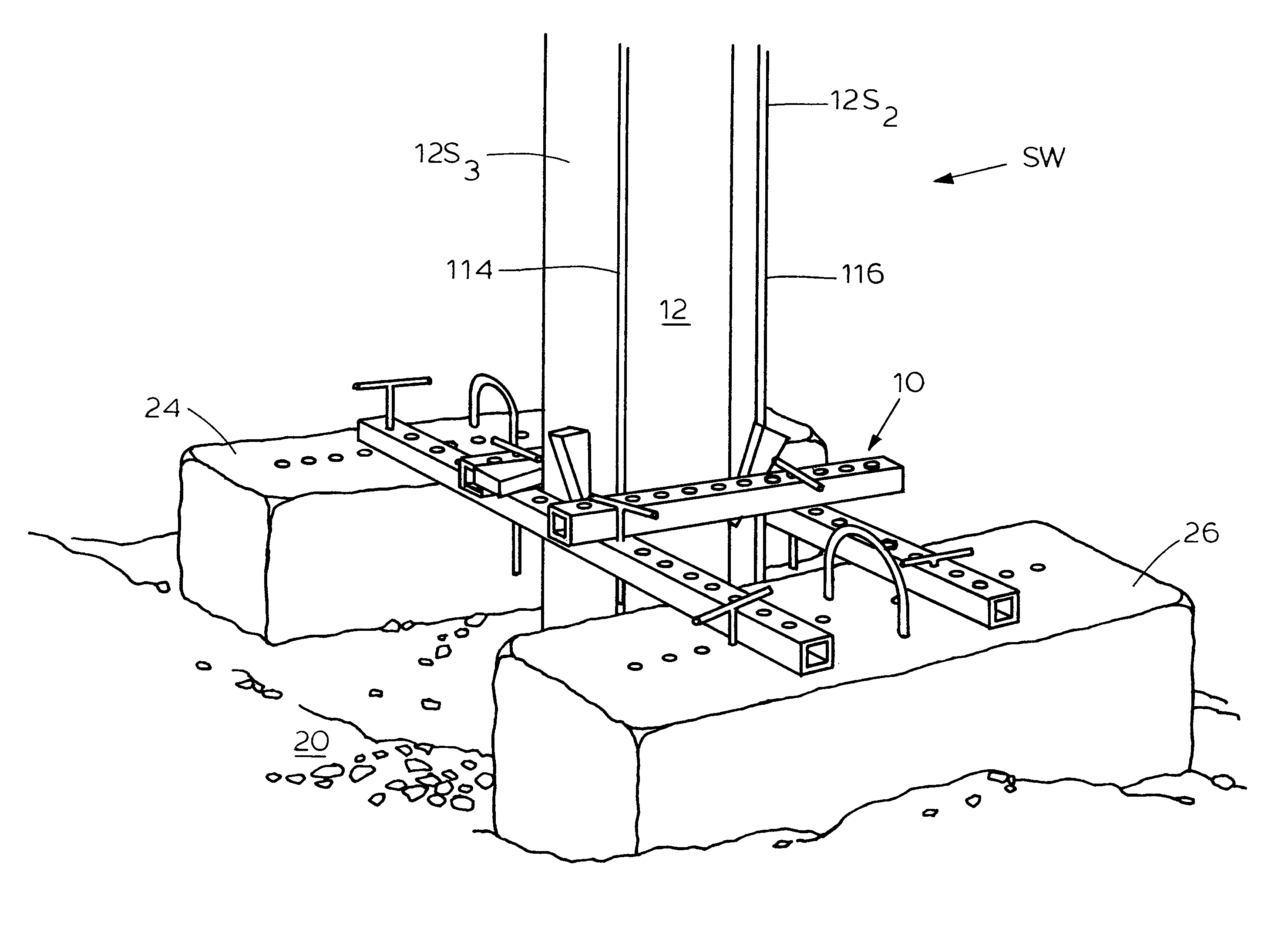
[0018]Referring to FIGS. 2-8, it can be understood that the principles of the present invention are embodied in a support system 10 for a column 12 which supports a structure, such as a soundwall SW (see FIGS. 7 and 8) or the like. As can be understood from FIGS. 4, 5 and 6, column 12 has surfaces 12S1, 12S2, 12S3 and 12S4 which are upright during erection of the column and which are oriented vertically when the column is in use.

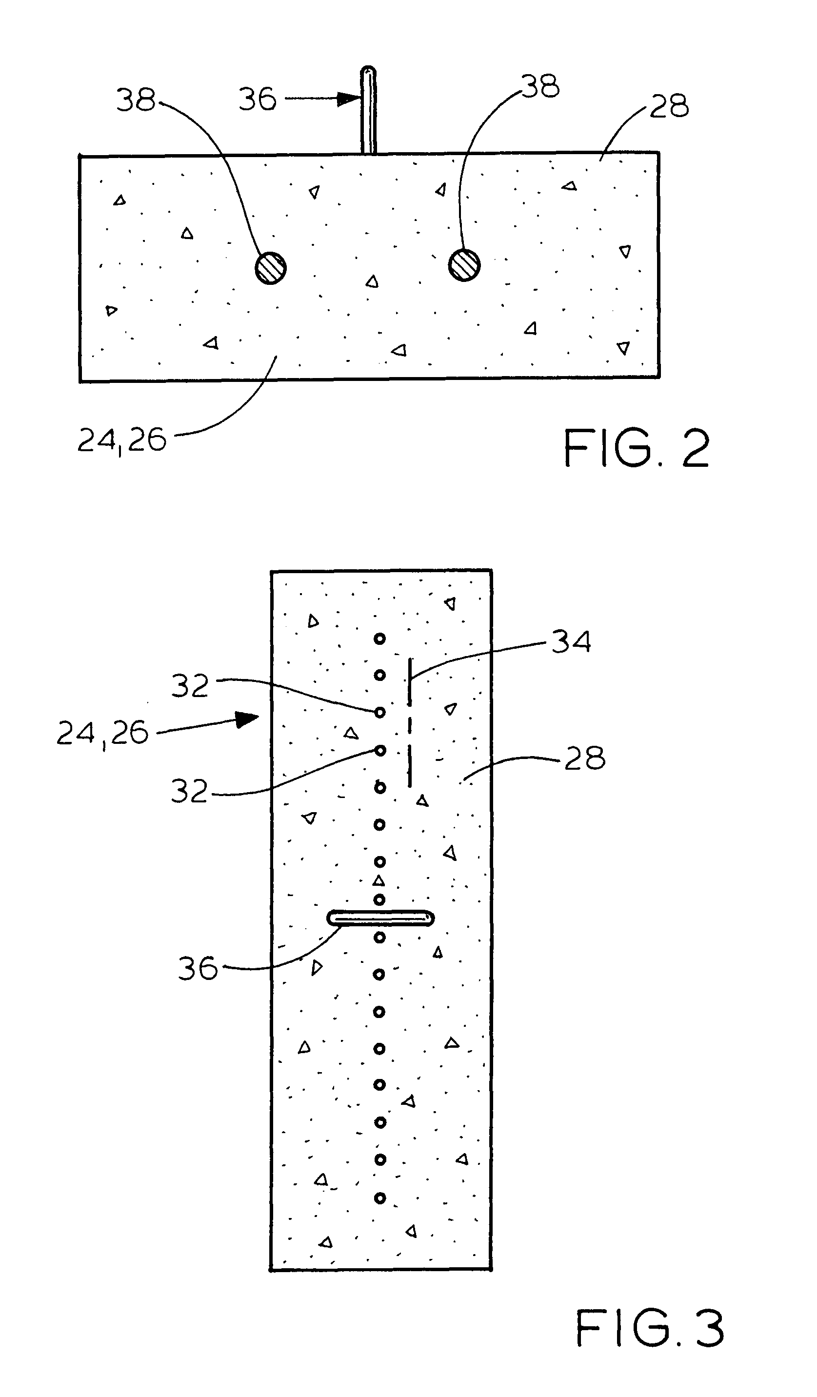
[0019]System 10 comprises a level surface 20, such as a leveled portion of the ground or the like. Two concrete anchor blocks 24 and 26 are located on the level surface. Each anchor block has a top face 28 which is co-level with the top face of the other anchor block. The anchor blocks are spaced apart from each other and define a gap 30 therebetween. Each anchor block includes a plurality of anchor holes 32 which are spaced apart from each other along a longitudinal axis 34 of the anchor block. A lifting hook 36 is located on top surface 28 of each anchor b...


PUM


Abstract

A system and method which positions and orients a wall post or column during positioning and supports the post after it has been positioned. The system embodying the principles of the present invention is set and contacts surfaces of the post. The system includes two monolithic one-piece anchor blocks located on a level surface to have top faces thereof located co-level with each other and tie and cross rods each of which has a surface that is vertically oriented when in use and which abuttingly engages a corresponding surface of the post when in use. At least one tie rod is connected to the anchor block top faces and the cross rod is attached to the tie rod. The tie rod is located at a desired position relative to a reference plane and the cross rod is located at a desired location relative to a reference location. The post is located between the two anchor blocks and in abutting contact with the vertically oriented surfaces of the rods. A second tie rod can be mounted on the anchor blocks prior to the connection of the first cross rod to the tie rods. The system automatically locates the post in a desired location and automatically levels the column or post so no additional adjustments are required. The system weight, including the weight of the anchor blocks, prevents shifting or movement of the post during set up.

Description

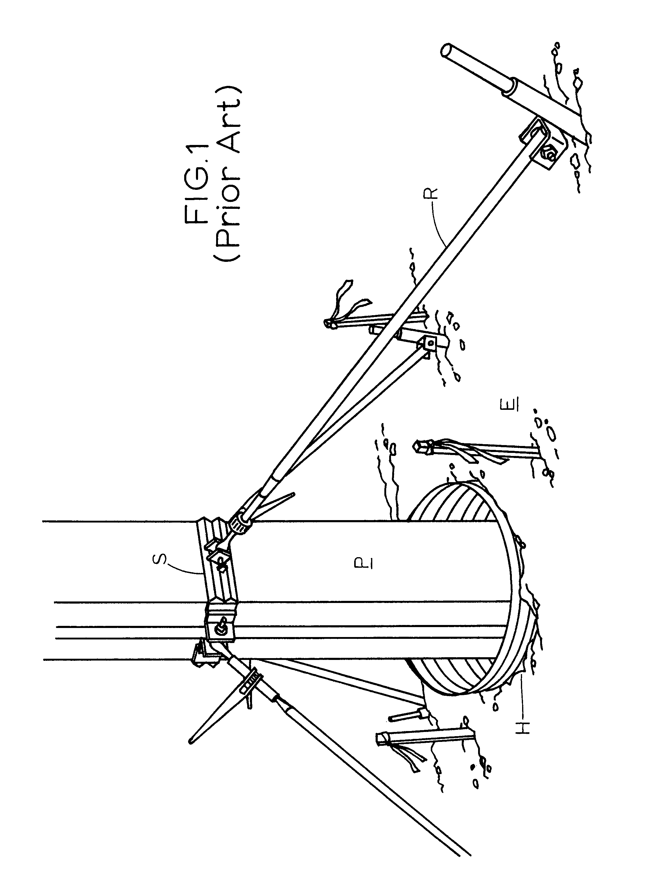
TECHNICAL FIELD OF THE INVENTION[0001]The present invention relates to the general art of static structures, and to the particular field of erecting columns or posts.BACKGROUND OF THE INVENTION[0002]Posts and columns are used in many situation, including supporting structures, supporting signs and fences as well as many other uses. If a post or column is used to support a massive structure, that post or column must, itself, be firmly and securely anchored and supported. It is noted that the terms “post” and “column” will be used interchangeably in this disclosure.[0003]If a post or column is used to support a massive structure, such as a soundwall, the current method of erecting that post or column is shown in FIG. 1 and proceeds as follows: a hole H is drilled in the earth E for post embedment; a post P is then raised by a crane or other mechanical means and is set in the drilled earth; concrete is poured into the hole around the post; and if necessary, rebar is placed around the p...

Claims


Application Information

Patent Timeline
IPC IPC(8): E02D27/42E04G23/04
CPCE02D27/42E04G21/185
Inventor LEIVA, MANUEL
Owner LEIVA MANUEL
Learn More