Airtightness test device and method for combustion chamber nozzle

An air tightness test and combustion chamber technology, which is applied in the direction of measuring the acceleration and deceleration rate of the fluid and using the liquid/vacuum degree for liquid tightness measurement, etc. The effect of avoiding dislocation and deformation, reducing labor intensity and shortening labor time

Active Publication Date: 2016-03-16
SHENYANG LIMING AERO-ENGINE GROUP CORPORATION
View PDF5 Cites 14 Cited by
  • Summary
  • Abstract
  • Description
  • Claims
  • Application Information

AI Technical Summary

Problems solved by technology

[0002] After the main combustion chamber of a certain engine is tested, it is necessary to check the sealing of the nozzle. Before the inspection, the nozzle needs to be disassembled from the fuel pipe, and then the sealing of a single nozzle is checked with kerosene. Each nozzle has multiple nozzles. It takes a long time to do the sealing test, and after the sealing inspection, the fuel pipe needs to be re-calibrated and connected to the inlet nozzle of the nozzle. This repeated disassembly and assembly is very likely to cause dislocation and deformation of the fuel pipe, and the nozzle of the fuel nozzle. Leakage, in severe cases, will cause the fuel pipe to break
Moreover, when carrying out the sealing test on the combustion chamber nozzle, most of them use oil as the medium to carry out the sealing test. Generally, the test is carried out on a single nozzle. The test time is long, and the oil and gas volatilize and pollute, which will cause a lot of economic waste and personal injury

Method used


Image

  • Airtightness test device and method for combustion chamber nozzle

Examples


Embodiment Construction

[0021] The present invention will be described in further detail below in conjunction with embodiment.

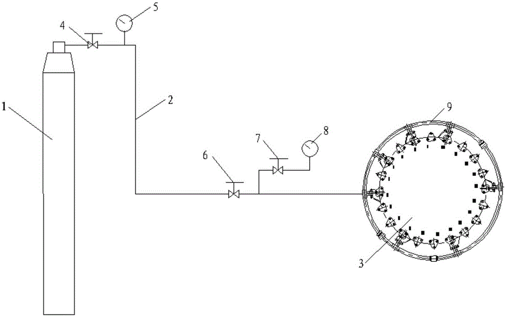
[0022] according to figure 1 As shown, an airtight test device for a combustion chamber nozzle includes a gas storage bottle 1, the gas storage bottle 1 is connected to the fuel main pipe of the main combustion chamber 3 through a pipeline 2, and the gas storage bottle 1 and the fuel oil main pipe 9 are connected sequentially on the pipeline A total pressure valve 4, a total pressure gauge 5 and a constant pressure valve 6 are arranged in series, and a pressure gauge valve 7 and a sealed pressure gauge 8 are arranged in parallel on the pipeline connecting the constant pressure valve 6 and the fuel main pipe 9.

[0023] Filled in the gas cylinder 1 is nitrogen.

[0024] The method for carrying out the airtight test of the combustion chamber nozzle by using the airtight test device of the above-mentioned combustion chamber nozzle, the specific steps are as follows:

[0025]...


PUM


Abstract

The invention provides an airtightness test device and method for a combustion chamber nozzle. The device comprises a gas storage bottle, the gas storage bottle is connected with a fuel manifold of a main combustion chamber through a pipe, a total-pressure valve, a total pressure gauge and a constant-pressure valve are successively connected in series on the pipe connected with the gas storage bottle and the fuel manifold, a pressure gauge valve and a seal pressure gauge are disposed on the pipe, which is connected with the constant-pressure valve and the fuel manifold, in a parallel connection manner, and a nitrogen gas is filled in the gas storage bottole. Through adoption of an overall seal test of the fuel manifold, a seal test of a nozzle is performed on the condition that the combustion chamber nozzle is not decomposed, labor intensity when airtightness check of the nozzle is performed is reduced, labor time is greatly shortened, damage of an oil gas on a human body is also reduced, auxiliary materials and labor cost are saved, and malposition, deformations and even fractures, which are resulted from the fact that fuel branched pipes are detached and mounted on the nozzle repeatedly, of the fuel branched pipes are prevented.

Description

Technical field: [0001] The invention relates to the technical field of engine repair, in particular to an airtight test device and method for a combustion chamber nozzle. Background technique: [0002] After the main combustion chamber of a certain engine is tested, it is necessary to check the sealing of the nozzle. Before the inspection, the nozzle needs to be disassembled from the fuel pipe, and then the sealing of a single nozzle is checked with kerosene. Each nozzle has multiple nozzles. It takes a long time to do the sealing test, and after the sealing inspection, the fuel pipe needs to be re-calibrated and connected to the inlet nozzle of the nozzle. This repeated disassembly and assembly is very likely to cause dislocation and deformation of the fuel pipe, and the nozzle of the fuel nozzle. Leakage, in severe cases, will cause the fuel pipe to break. Moreover, when carrying out the sealing test on the combustion chamber nozzle, most of them use oil as the medium to...

Claims


Application Information

Patent Timeline
Patent Type & Authority Applications(China)
IPC IPC(8): G01M3/26
CPCG01M3/26
Inventor 任武王虎威吕晶尚小丽赵叙涵
Owner SHENYANG LIMING AERO-ENGINE GROUP CORPORATION
Why Eureka
Try Eureka