Surface mount-type vibration motor and fixation structure for surface mount-type vibration motor

a vibration motor and surface mount technology, applied in the direction of mechanical vibration separation, printed circuit non-printed electric components association, etc., can solve the problems of easy separation, easy separation, and large size of surface mount-type vibration motors, so as to prevent the generation of undesirable noise due to board vibration, secure the vibration, and reduce the effect of vibration

Inactive Publication Date: 2010-11-02
NAMIKI PRECISION JEWEL CO LTD
View PDF7 Cites 13 Cited by
  • Summary
  • Abstract
  • Description
  • Claims
  • Application Information

AI Technical Summary

Benefits of technology

[0023]According to the invention, since molten solder infiltrates into the aforementioned spaces surrounded by the aforementioned first contact section and the aforementioned second contact section to enlarge a solder extending area during the time when the solder is solidified to form a swelling due to surface tension, the aforementioned first contact section and the aforementioned second contact section can be strongly solder-bonded with the surface of the aforementioned board. Therefore, even if the aforementioned surface mount-type vibration motor is subjected to a load that acts to separate it from the aforementioned board, the solder portion solidified forming a swelling can stably retain the aforementioned surface mount-type vibration motor. In other words, according to this invention, since the solder portion solidified forming a swelling can stably retain the aforementioned surface mount-type vibration motor when the aforementioned surface mount-type vibration motor is subjected to a load in a direction along the aforementioned board, an effect that the aforementioned surface mount-type vibration motor can be prevented from separating from the aforementioned board even if the aforementioned surface mount-type vibration motor is subjected to the load in the direction along the aforementioned board is obtained.
[0024]According to the invention, since the aforementioned elastic holder is provided, a load applied to the aforementioned motor holder from the aforementioned vibration motor body can be absorbed by the aforementioned elastic holder. Therefore, the load applied to the portion where the aforementioned surface mount-type vibration motor is soldered to the aforementioned board can be further reduced. In other words, according to this invention, since the aforementioned elastic holder can reduce the load transmitted to the aforementioned motor support section of the aforementioned motor holder through the aforementioned motor holding section, the load applied to the portion where the aforementioned motor support section is soldered to the aforementioned board can be reduced. Therefore, the effect that the aforementioned surface mount-type vibration motor is prevented from separating from the aforementioned board is obtained.
[0025]According to the invention, since a pair of power supply terminals having the aforementioned bending sections are provided, the load applied to the portion where the aforementioned power supply terminals are soldered to the aforementioned board can be absorbed by the aforementioned bending sections. Therefore, the load applied to the portion where the aforementioned power supply terminals are soldered to the aforementioned board can be reduced to produce an effect of vibration absorption similar to the aforementioned motor holder. In other words, according to this invention, since a pair of power supply terminals having the aforementioned bending sections are provided, the load applied to the portion where the aforementioned power supply terminals are soldered to the aforementioned board can be absorbed by the aforementioned bending sections. Therefore, the load applied to the portion where the aforementioned power supply terminals are soldered to the aforementioned board can be reduced to produce an effect of vibration absorption similar to the aforementioned motor holder.
[0026]According to the invention, since the aforementioned elastic support body is provided, when the housing case is assembled, a load inclining the motor holding section in the plane direction of the board is supported and the load applied to the aforementioned motor holder is absorbed or received by the aforementioned elastic support body, and, in addition, vibration of the aforementioned vibration motor body can efficiently be transmitted to the housing case side during the motor operation. Further, generation of undesirable noise due to board vibration can be prevented. At the same time, according to this invention, since the aforementioned elastic support body can reduce the load transmitted to the aforementioned motor support sections of the aforementioned motor holder through the aforementioned motor holding section, the load applied to the portion where the aforementioned motor support section is soldered to the aforementioned board can be reduced. Therefore, the effect that the aforementioned surface mount-type vibration motor is prevented from separating from the aforementioned board is obtained.
[0027]According to the invention, since the aforementioned power supply terminal having the aforementioned bending section is provided, the load applied to the portions where the aforementioned power supply terminals are soldered to the aforementioned board can be absorbed by the aforementioned bending sections. Therefore, the load applied to the portions where the aforementioned power supply terminals are soldered to the aforementioned board can be reduced. Thus, the effect that the aforementioned power supply terminals of the aforementioned surface mount-type vibration motor is prevented from separating from the aforementioned board is obtained.
[0028]According to the invention, bonding strength between the aforementioned board and the aforementioned surface mount-type vibration motor can be maintained high, and by filling the clearance between the aforementioned case and the vibration motor with an elastic member of the elastic support body, loads applied to the aforementioned surface mount-type vibration motor almost in all directions can stably be borne by the aforementioned elastic support body and a possibility that the motor is separated from the board due to shock or vibration load can be lowered. This structure is also excellent in securely transmitting the vibration load from the motor to the housing case. At the same time, since it is possible to reduce the load applied to the portion where the aforementioned power supply terminal is soldered to the board, an effect that the aforementioned power supply terminal of the aforementioned surface mount-type vibration motor can be prevented from separating from the aforementioned board.

Problems solved by technology

However, the surface mount-type vibration motor is far larger than other general electronic components in size and weight.
Thus, the surface mount-type vibration motor has a problem that it is easily separated from the bonding surface of a board because a soldered portion is subjected to a load larger than that applied to a soldered portion of other conventional electronic components.
Therefore, since the soldered portion is subjected to larger gyratory load in comparison with other electronic components, the surface mount-type vibration motor has a major problem that it can separate more easily.
The contact portion where the aforementioned power supply terminal for the surface mount-type vibration motor is soldered to the power supply land provided on a board also has a problem of separation similar to the above.
Especially, when the contact portion on the board surface soldered to the above power supply terminal happens to be separated, there arises a significant problem wherein the vibration motor body becomes inactive due to poor electrification.

Method used


Image

  • Surface mount-type vibration motor and fixation structure for surface mount-type vibration motor
  • Surface mount-type vibration motor and fixation structure for surface mount-type vibration motor
  • Surface mount-type vibration motor and fixation structure for surface mount-type vibration motor

Examples


Embodiment Construction

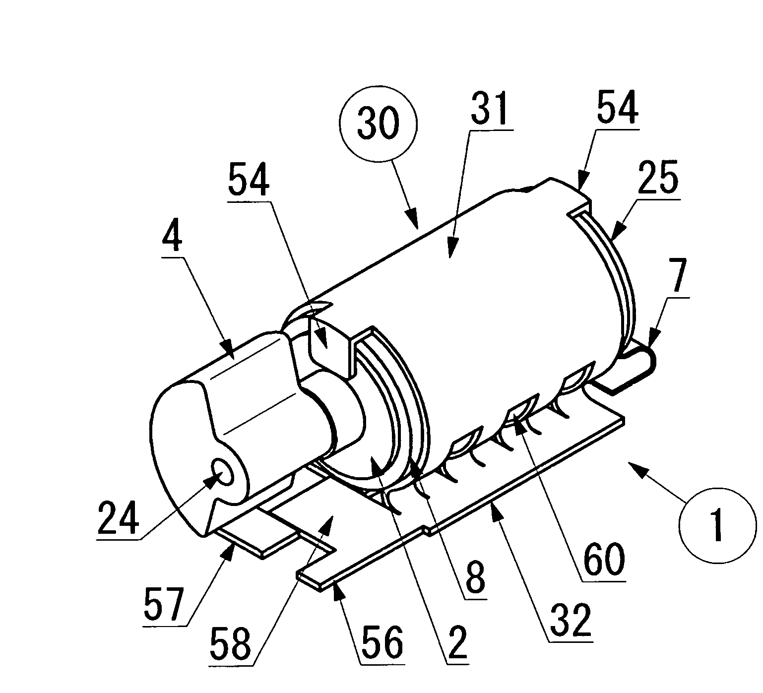
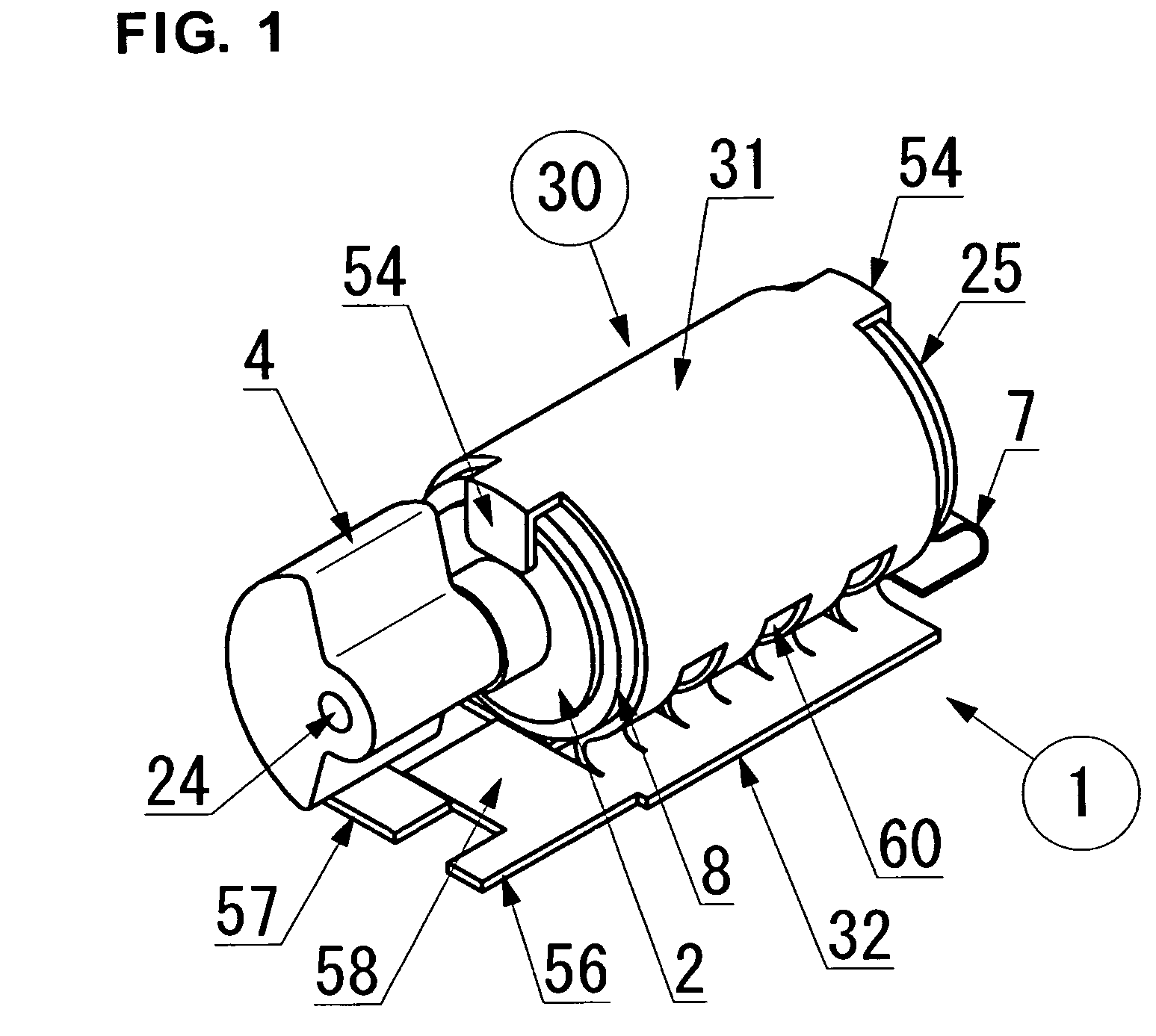
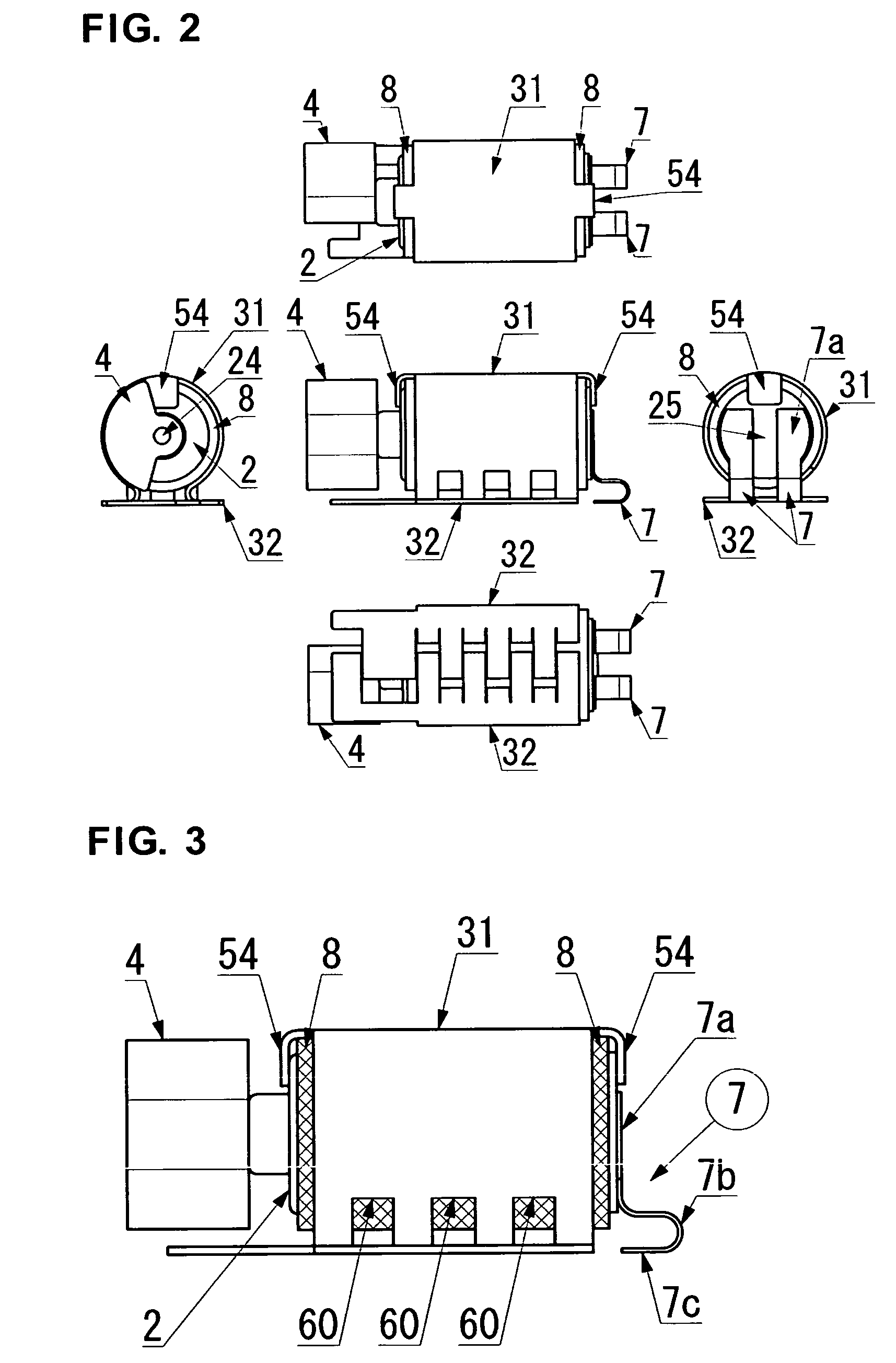
[0039]Now an embodiment relating to a surface mount-type vibration motor and an installation structure for a surface mount-type vibration motor according to this invention are described in detail referring to FIGS. 1 through 10.

[0040]FIGS. 1 through 3 show an example of a surface mount-type vibration motor relating to the embodiment. The surface mount-type vibration motor 1 is a surface mount component to be reflow-soldered to a solder bonding surface on a board on which cream solder is printed, or on a board of so-called circuit board 3 (see FIG. 9), and is an electronic component for a sound-less vibration alarm mainly provided to mobile devices. A vibration motor body 2 is provided inside the surface mount-type vibration motor 1 as shown in FIG. 4. This vibration motor body 2 is provided with an almost cylindrical motor housing 21 for containing a major portion of a rotation drive mechanism component.

[0041]A bearing section (not illustrated) is arranged inside the motor housing 2...


PUM


Abstract

A surface mount-type vibration motor and an installation structure for a surface mount-type vibration motor, where soldered portions are prevented from separating from a circuit board without requiring any design change in a vibration motor body. A section where a motor holding section of a motor holder and motor support sections of the motor holder are connected is bent in an arc shape having elasticity to form the motor holder, the motor holding section holding a vibration motor body to which an elastic holder is attached, the motor support sections being arranged along a circuit board. First contact sections and second contact sections are formed in the connection section such that distal ends of the first and second contact sections are of a band-like shape projecting toward the inside of the vibration motor body. The motor holder reduces a load applied to portions where the surface mount-type vibration motor is soldered to the circuit board and also improves bonding strength.

Description

TECHNICAL FIELD[0001]This invention relates to a surface mount-type vibration motor and a fixation structure for the surface mount-type vibration motor, more specifically to a surface mount-type vibration motor provided with a motor holder to be soldered to a circuit board and an installation structure of the surface mount-type vibration motor.BACKGROUND ART[0002]Recently, electronic parts for electronic devices are often designed as a board surface mount-type using reflow solder for the convenience of assembly. These electronic parts are designed so that cream solder is placed on a specified position of a printed circuit board (hereafter referred to as “board” as required), and after processing, each electronic device is bonded to the board by cream solder melted in a heating furnace.[0003]In addition, the vibration motor body recently used by some mobile phones is also designed as a surface mount-type component comprising a motor holder having a motor holding section for covering ...

Claims


Application Information

Patent Timeline
Patent Type & Authority Patents(United States)
IPC IPC(8): H02K7/065B06B1/16H02K5/00H02K5/22H02K7/06H05K1/18H05K3/30
CPCH02K5/00H02K7/061H02K5/225H05K3/301H02K2211/03H02K7/065H02K7/075
Inventor UCHIUMI, HIDEHIROMORITA, KAZUOSUZUKI, TOSHIOAOYAGI, TOMOHIDEKOGAWA, TAKESHIKUDO, MITSUGU
Owner NAMIKI PRECISION JEWEL CO LTD
Why Eureka
Try Eureka