Underwater gun comprising a turbine-based barrel seal
a technology of turbine-based barrels and underwater guns, which is applied in the field of underwater guns, can solve the problems of inability to fire, material failure of the barrel, and the inability to meet the needs of water keeping,
- Summary
- Abstract
- Description
- Claims
- Application Information
AI Technical Summary
Benefits of technology
Problems solved by technology
Method used
Image
Examples
first embodiment
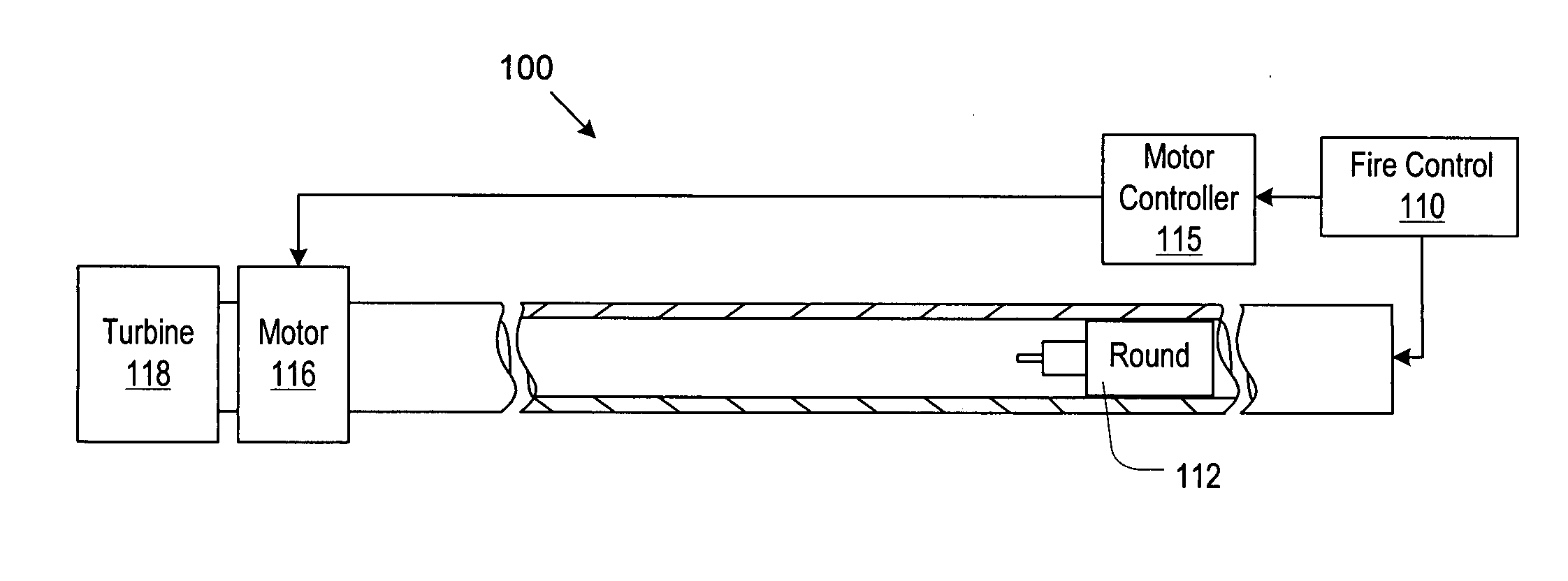
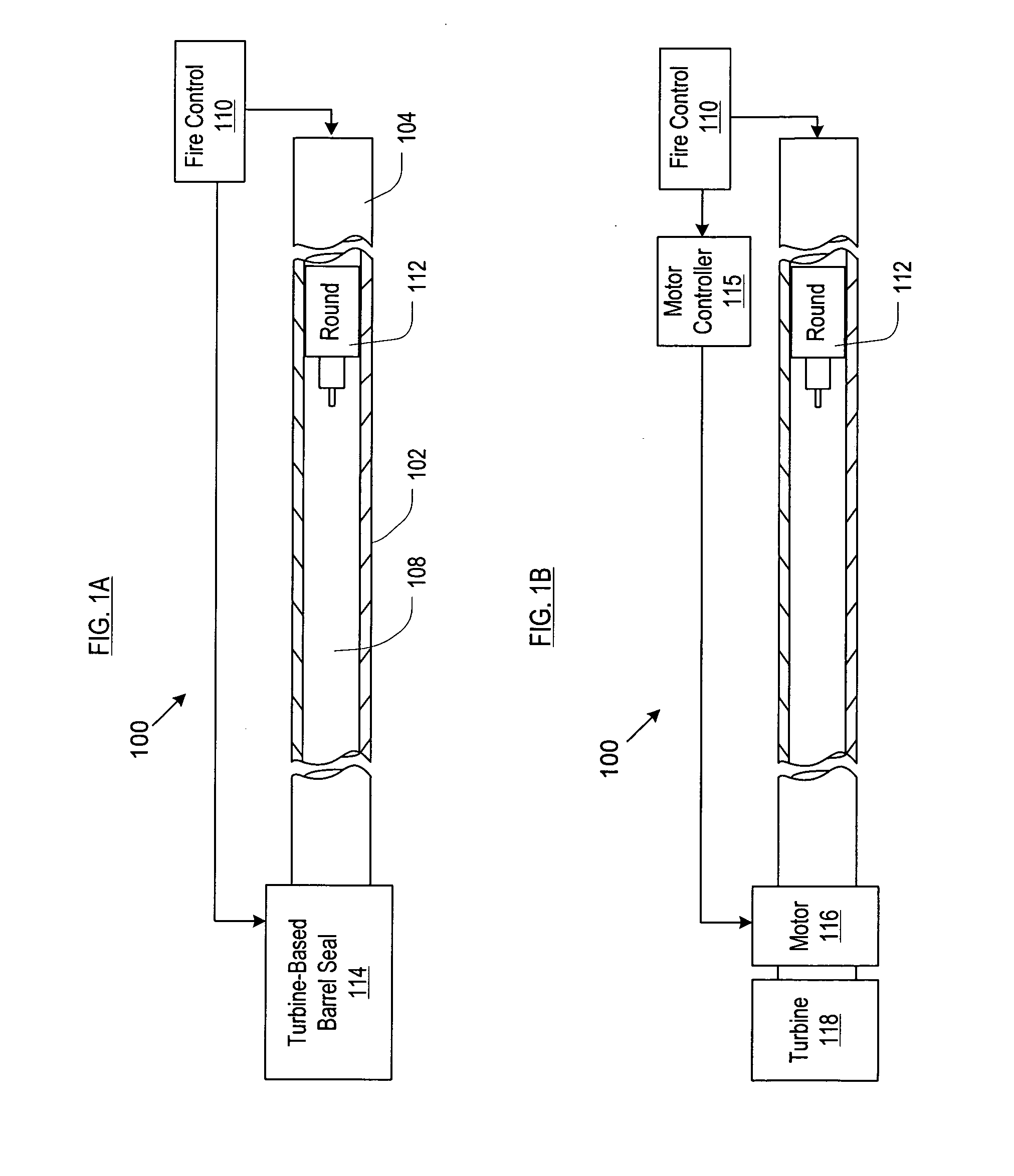
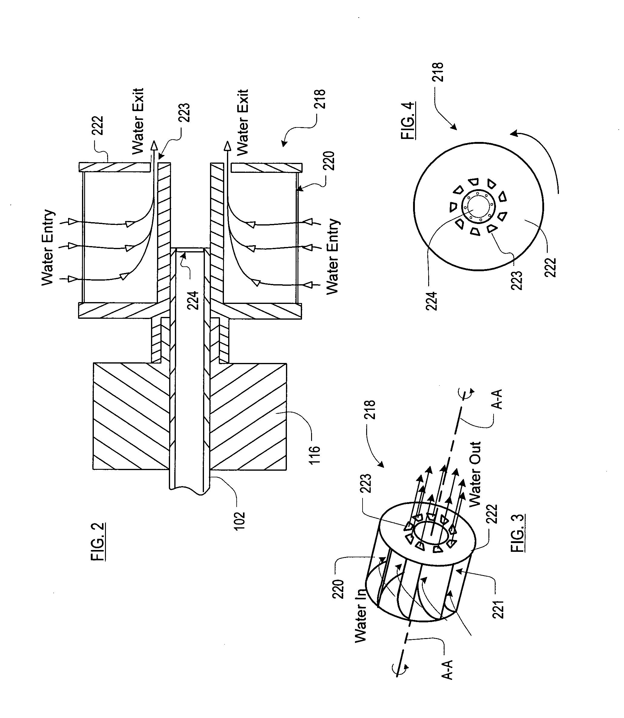
[0045]FIGS. 2 through 4 depict turbine-based barrel seal 114 of FIG. 1B. FIG. 2 depicts motor 116 and turbine 218 coupled to muzzle end of barrel 102. Rupture disk 224 is disposed at the end of barrel 102. FIG. 3 depicts a three-quarters perspective view of turbine 218 and FIG. 4 depicts a front end view of turbine 218.
[0046]Referring now to FIGS. 2 through 4, turbine 218 comprises a plurality of blades 220 that extend radially outward about spin axis A-A of the turbine. Blades 220 are curved to facilitate “scooping” water from the surroundings. Channel 221 is formed between adjacent turbine blades 220.
[0047]A plurality of orifices 223 are disposed in forward wall 222 of turbine 218, one orifice in each channel 221. Orifices 223 are situated at the most radially-inward portion of forward wall 222 (i.e., at the bottom of each channel 221). As a consequence, the diameter of the “ring” of orifices 223 is only slightly larger than the diameter of barrel 102.
[0048]Before gun 100 is initi...
second embodiment
[0051]FIGS. 5 through 7 depict turbine-based barrel seal 114 of FIG. 1B. FIG. 5 depicts a cross-sectional view of motor 116 and turbine 518 coupled to muzzle end of barrel 102. Rupture disk 224 is disposed at the end of barrel 102. FIG. 6 depicts a cross-sectional view of turbine 518 in operation wherein water vapor forms as water contacts the turbine blades. FIG. 7 depicts a cross-sectional view of turbine 518 in operation, wherein the vapor bubbles that are formed migrate to the spin axis of the turbine and leave the turbine in equilibrium with water that enters the turbine.
[0052]Referring now to FIGS. 5 through 7, turbine 518 comprises a plurality of internally disposed turbine blades 528 that extend radially inward from wall 526.
[0053]In operation, turbine is spun up to a desired operating speed via motor 116. Water enters turbine 518 through orifice 530. The spin of the turbine 518 forces the water radially outward such that water contacts blades 528. The operating speed of tur...
third embodiment
[0058]FIGS. 8 through 10 depict turbine-based barrel seal 114 of FIG. 1B. FIG. 8 depicts a cross-sectional view of motor 116 and turbine 818 coupled to muzzle end 106 of barrel 102. Rupture disk 224 is disposed at the end of barrel 102. FIG. 9 depicts a cross-sectional view of turbine 818 in operation. FIG. 10 depicts a front end view of 818 in operation.
[0059]Referring now to FIGS. 8 through 10, turbine 818 comprises a plurality of internally-disposed turbine blades 828 that extend radially inward from wall 826. A plurality of orifices 830 are disposed in wall 826 between blades 828. In the embodiment that is depicted in these Figures, a grouping of four orifices 830 is disposed at ninety-degree intervals around wall 826 between successive blades 828 (see, FIG. 10). In some other embodiments, the grouping contains a different number of orifices 830 (e.g., 7, etc.) and in some additional embodiments, the groupings are disposed at different axial locations than is shown in FIGS. 8 an...
PUM
 Abstract
Description
Claims
Application Information
 - R&D
- Intellectual Property
- Life Sciences
- Materials
- Tech Scout
- Unparalleled Data Quality
- Higher Quality Content
- 60% Fewer Hallucinations
Browse by: Latest US Patents, China's latest patents, Technical Efficacy Thesaurus, Application Domain, Technology Topic, Popular Technical Reports.
© 2025 PatSnap. All rights reserved.Legal|Privacy policy|Modern Slavery Act Transparency Statement|Sitemap|About US| Contact US: help@patsnap.com


