
Roof with intergrated device for ventilating and cooling a motor vehicle passenger compartment

a technology for passenger compartments and roofs, which is applied in vehicle heating/cooling devices, machines using electric/magnetic effects, light and heating apparatus, etc. it can solve the problems of complex construction, limited degree, and high cost of production, and achieves the effect of simple structure and economical production

Inactive Publication Date: 2010-11-23
WEBASTO AG
View PDF14 Cites 5 Cited by
  • Summary
  • Abstract
  • Description
  • Claims
  • Application Information

AI Technical Summary

Benefits of technology

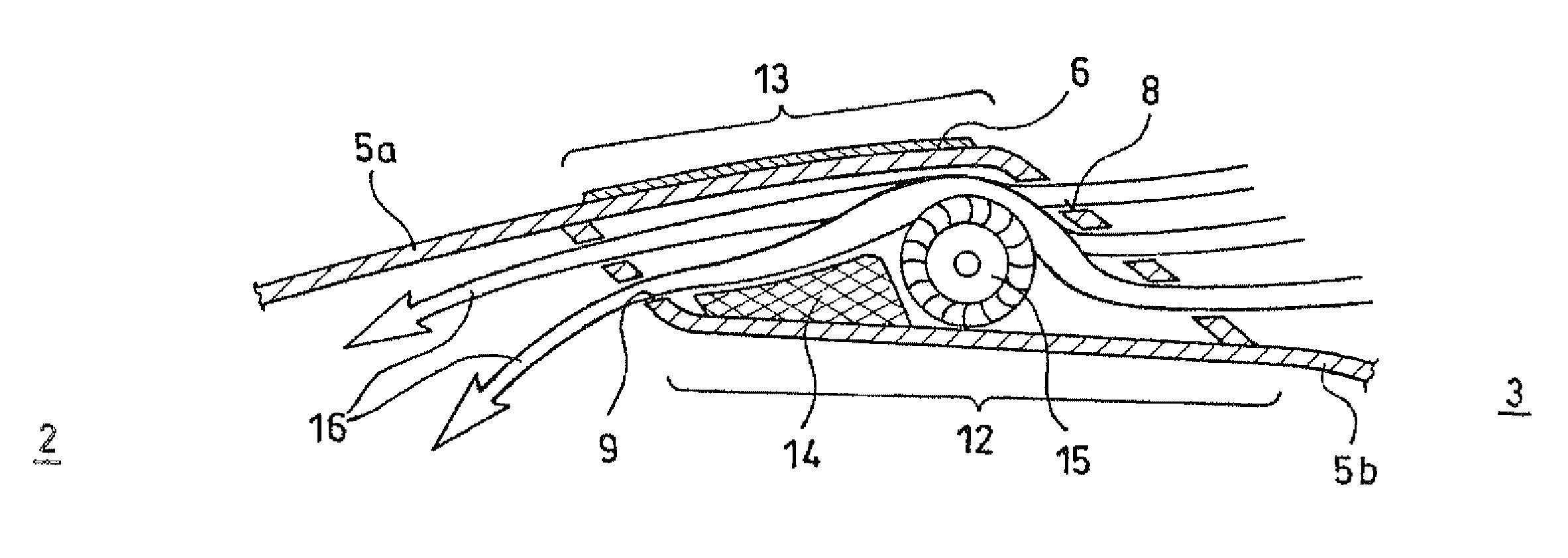
The invention is a device for ventilating and cooling the interior of a motor vehicle that allows for effective cooling of the vehicle interior, even at high outside temperatures. The device has a simple structure and is economical to produce. It includes an air guide channel with at least one fan for taking in outside air and at least one cooling element for cooling the air. The air guide channel is restricted to the rear area of the vehicle roof and has at least one fan and cooling element integrated within it. The device can be easily integrated into the rear area of a tiltable roof cover or for additional formation of a spoiler. The invention provides an effective solution for cooling the interior of a vehicle without reducing the height of the passenger compartment interior or burdening the vehicle battery.

Problems solved by technology

However, this outside air flow supply can, at most, achieve 50% cooling of the interior since the outside air—especially on hot days—contributes to cooling of the heated vehicle space only to a very limited degree due to strong heating.
These heat exchangers are limited in their cooling capacity depending on the temperature of the outside air.
Furthermore, these heat exchangers, in combination with cassettes, are complex in their construction and costly to produce.

Method used


Image

  • Roof with intergrated device for ventilating and cooling a motor vehicle passenger compartment
  • Roof with intergrated device for ventilating and cooling a motor vehicle passenger compartment
  • Roof with intergrated device for ventilating and cooling a motor vehicle passenger compartment

Examples


Embodiment Construction

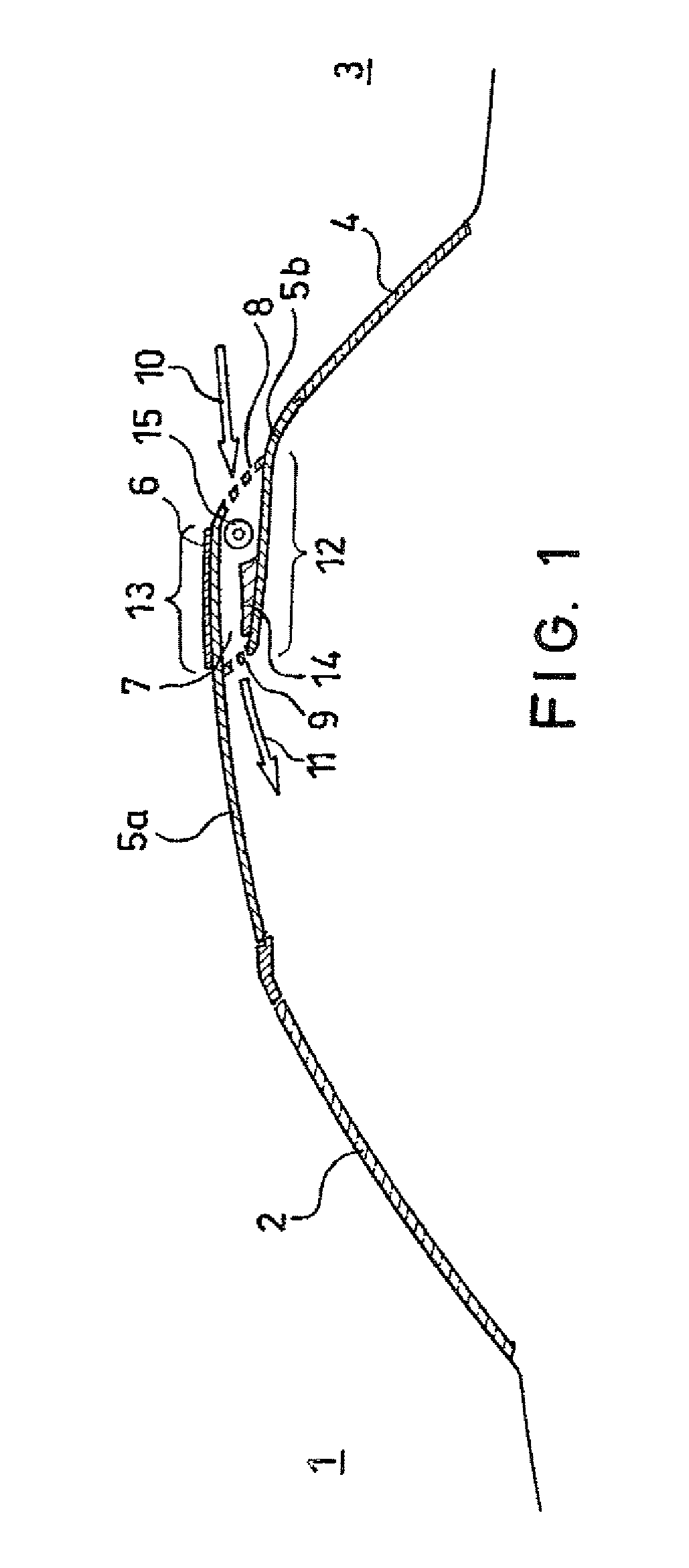
[0018]FIG. 1 shows a portion of a motor vehicle with a device according to an embodiment of the invention which has a windshield 2 towards the front 1 and a rear window 4 towards the back 3 of the vehicle.

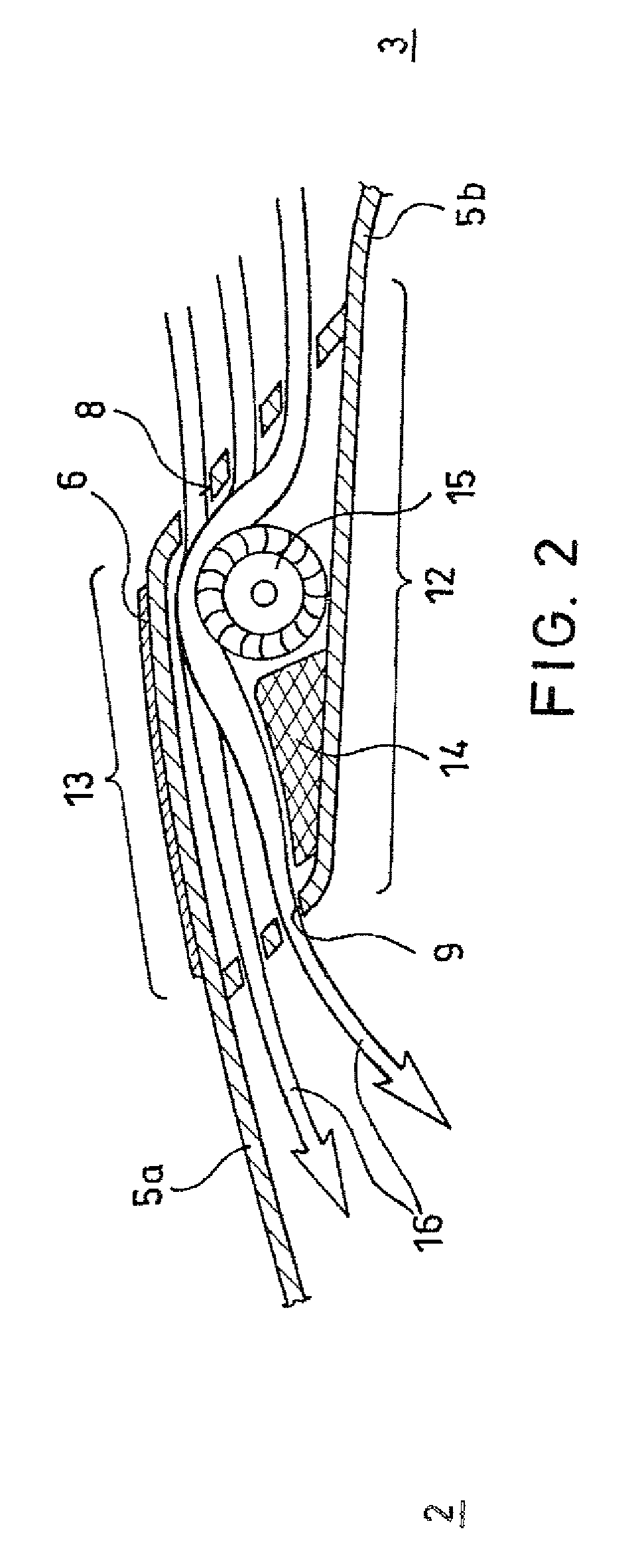
[0019]A vehicle roof portion 5a extends from the vehicle front 1 in the direction toward the rear 3 of the vehicle can be made tiltable in the manner of a conventional lifting sunroof and extends from the front of the vehicle to over a vehicle roof portion 5b which runs from the rear 3 of the vehicle toward the front 1 of the vehicle so that an air guide channel 7 is formed at the rear of the vehicle roof between a first section 12 of the roof portion 5b at the bottom and a second section 13 of the roof portion 5a at the top. Preferably, the air guide channel 7 extends across the entire width of the vehicle roof

[0020]The air guide channel 7 extends between air inlet openings 8 located in the rear and air outlet openings 9 facing toward the front 1 of the vehicle. The air flow defin...


PUM


Abstract

A device for ventilating and cooling the interior of a vehicle with at least one air guide channel (7) having air inlet openings (8) located in the rear of a solar cell equipped vehicle roof (5a, 5b), the air guide channel (7) being restricted to the rear area (3) of the vehicle roof (5a, 5b) and having at least one fan (15) for taking in outside air (10) and at least one cooling element (14) for cooling the air taken in. The bottom of the air guide channel (7) is formed by a first section (12) of a roof portion (5b) which extends from the vehicle rear toward the vehicle front (3, 1) and the top of the air guide channel (7) is formed by a second section (13) of a roof portion (5a) which extends from the vehicle front toward the vehicle rear (1, 3).

Description

BACKGROUND OF THE INVENTION[0001]1. Field of the Invention[0002]The invention relates to a device for ventilating and cooling the interior of a vehicle with air inlet openings located in the rear of a solar cell-equipped vehicle roof and with at least one air guide channel connected to it.[0003]2. Description of Related Art[0004]Conventionally, the interior of a vehicle is reached by blowing the outside air surrounding the vehicle into its interior, the cooling of the heated interior being achieved by the temperature difference between the outside and the inside temperature and the cooling action of the air flow. Devices for this supply and withdrawal of air from the outside to the inside and vice versa are known according to German Patent DE 40 22 928 C1 and corresponding to U.S. Pat. No. 5,248,278 and also for the roof area of a motor vehicle. Such devices generally have a fan which is located in the region of the roof cutout which can be closed with a conventional sliding roof co...

Claims


Application Information

Patent Timeline
Patent Type & Authority Patents(United States)
IPC IPC(8): F25B21/02B60H1/00B60H1/26
CPCB60H1/00428B60H1/262Y02T10/88
Inventor TESCHNER, HELMUTKOELBL, MICHAELPOLLAK, MARTINVILSMAYER, SVENKOGLER, RUPERTPAETZ, WERNERRENNER, ALFREDERBECK, GERITBOEHM, HUBERTLORENZ, STEFFEN
Owner WEBASTO AG
Learn More