Piezoelectric element, ink jet head, and ink jet recording device

a technology of ink jet and recording device, which is applied in the direction of piezoelectric/electrostrictive/magnetostrictive device, printing, electrical apparatus, etc., can solve the problems of non-uniform pressure generation from the pressure chamber region, electrode short circuit, and cracks in the lead electrode at the boundary between the pressure chamber and the peripheral wall

Active Publication Date: 2010-11-23
KONICA MINOLTA INC
View PDF31 Cites 4 Cited by
  • Summary
  • Abstract
  • Description
  • Claims
  • Application Information

AI Technical Summary

Benefits of technology

[0011]The invention is contrived to solve the above-mentioned problems. An object of the invention is to provide a piezoelectric element with high efficiency, high driving durability, and high reliability without causing cracks in a piezoelectric body in a region corresponding to an edge portion of a pressure chamber, a lead electrode, and an FPC substrate mounting portion.
[0013]According to the invention, in the piezoelectric element formed above the edge portion of the pressure chamber hole, a stress at the time of driving the piezoelectric element is reduced to prevent destruction due to cracks.

Problems solved by technology

However, in the above-mentioned conventional structures, when the upper electrode, the piezoelectric body, and the lower electrode are stacked and a portion (hereinafter, referred to as piezoelectric active region) for substantially generating pressure in the pressure chamber protrudes from the pressure chamber region to the outside of the peripheral wall of the pressure chamber (that is, to the outside of the edge portion of the pressure chamber), the pressure generated from the piezoelectric active region cannot be effectively transmitted to ink, thereby causing the non-uniform pressure generation from the pressure chamber region.
In addition, cracks can occur in the lead electrode at the boundary between the pressure chamber and the peripheral wall.
When cracks occur in the lead electrode, the lead electrode may be short-circuited or leak current may flow in the piezoelectric body.

Method used


Image

  • Piezoelectric element, ink jet head, and ink jet recording device
  • Piezoelectric element, ink jet head, and ink jet recording device
  • Piezoelectric element, ink jet head, and ink jet recording device

Examples


first embodiment

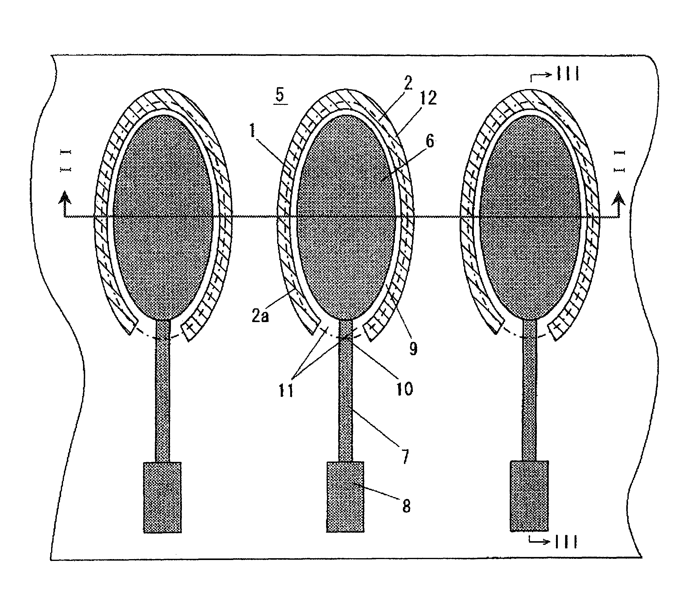
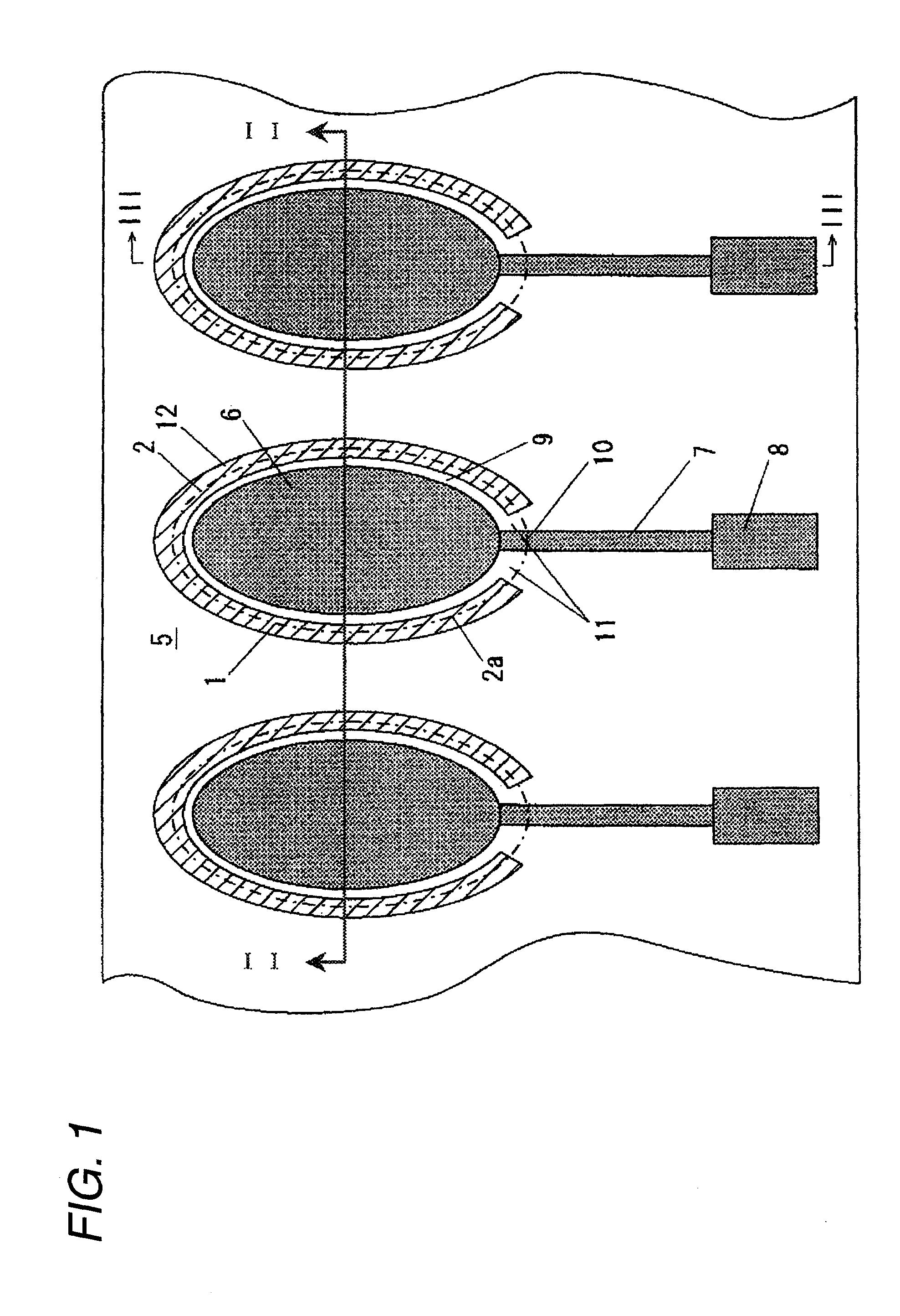
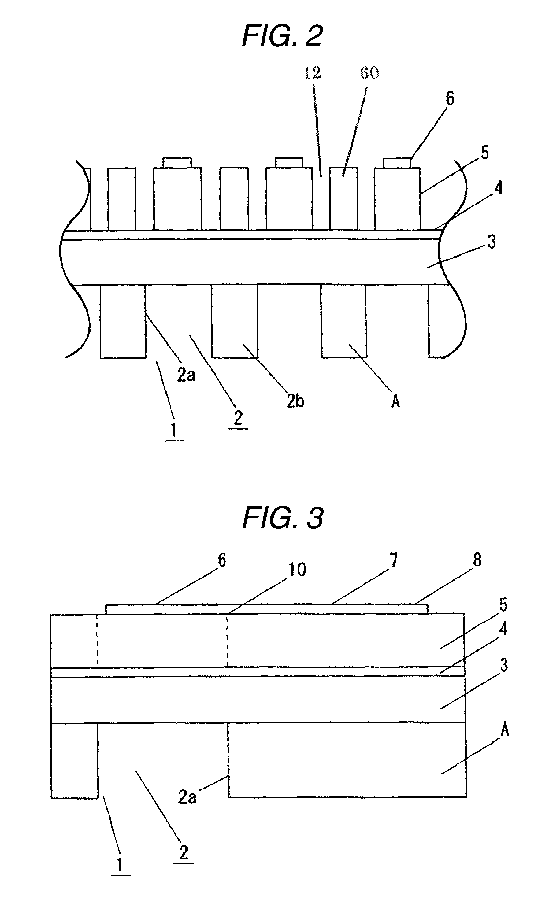
[0052]In order to improve deformation efficiency of a vibrating plate with the driving of a piezoelectric element, a structure for reducing the thickness of the vibrating plate in a peripheral portion of the piezoelectric element has been suggested. However, such a structure may cause an occurrence of cracks at the boundary between a pressure chamber and a peripheral wall thereof.

[0053]The problem with the cracks may easily occur particularly when a piezoelectric body is formed by the use of a film forming technology. This is because a layered piezoelectric body (piezoelectric thin film) formed by the use of the film forming technology is very thin and thus the residual stress in the course of a film forming process remains. Therefore, the rigidity thereof is smaller than that when the piezoelectric body is formed by adhesion. Particularly, cracks tend to easily occur in the piezoelectric body having a column-shaped structure formed by controlling crystal growth.

[0054]When the piezo...

second embodiment

[0235]Hereinafter, a second embodiment of the invention will be described in detail.

[0236]It is possible to further enhance the reliability of the piezoelectric element by applying the second embodiment to the piezoelectric element according to the first embodiment.

[0237]When a high voltage is applied to the piezoelectric element in a state where it is exposed to a high-humidity atmosphere for a long time, an electrical insulation property of the piezoelectric body is deteriorated, thereby causing the dielectric breakdown. Accordingly, various studies for preventing the dielectric breakdown have been made.

[0238]As one countermeasure, in order to prevent migration of an electrode material into the piezoelectric body which is greatly associated with the dielectric breakdown, gold or platinum that hardly migrates is used as the electrode material. However, even when the migration of the electrode material to the piezoelectric body is prevented using gold or platinum as the electrode ma...


PUM


Abstract

A piezoelectric element includes a pressure chamber member that has an opening communicating with a nozzle, a vibrating plate that is disposed on the pressure chamber member so as to cover the opening, a lower electrode that is disposed on the vibrating plate, a piezoelectric body that is disposed on the lower electrode, an upper electrode that is disposed on the piezoelectric body and in a region opposed to the opening, and a lead electrode that is disposed on the piezoelectric body, that extends from the upper electrode, and that has a width smaller than that of the upper electrode. The piezoelectric body includes a groove portion that is disposed in a predetermined region along an edge portion of the opening and an inactive region (piezoelectric inactive region) that is a region other than the groove portion, that is disposed along the edge portion of the opening, and that does not substantially serve as a piezoelectric element. The lead electrode is disposed in the piezoelectric inactive region.

Description

BACKGROUND[0001]1. Field of the Invention[0002]The present invention relates to a piezoelectric element used in a piezoelectric actuator such as a piezoelectric vibrator and a liquid ejecting device, a semiconductor recording device, and a pyroelectric infrared detecting device, an ink jet head using the piezoelectric element, and an ink jet recording device having the ink jet head.[0003]2. Description of the Related Art[0004]In a piezoelectric element, generally, a layered piezoelectric body (such as lead zirconate titanate (PZT)) is disposed between two electrodes (referred to as lower electrode and upper electrode in the following description). The piezoelectric body serves to convert mechanical energy into electrical energy or to convert electrical energy into mechanical energy. The piezoelectric element with such a function is used for various devices.[0005]Piezoelectric ceramics such as lead zirconate titanate (PZT) is used as a material of the piezoelectric body. Lead-based p...

Claims


Application Information

Patent Timeline
Patent Type & Authority Patents(United States)
IPC IPC(8): B41J2/045
CPCH01L41/0973B41J2/14233B41J2/161B41J2/1623B41J2/1628B41J2/1629B41J2/1631B41J2/1632B41J2/1635B41J2/1642B41J2/1643B41J2/1645B41J2/1646H01L41/047B41J2202/11H10N30/875H10N30/2047
Inventor HARA, SHINTAROUWATANABE, OSAMUSADAMATSU, KAZUMIHORIO, HIDEAKIFUJII, EIJI
Owner KONICA MINOLTA INC
Why Eureka
Try Eureka