Anti-scatter grid

a grid and anti-scatter technology, applied in the field of anti-scatter grids, can solve the problems of image faults, reduced ability to detect fine differences in contrast, and loss of primary radiation at the edges of recorded images, and achieve the effect of low cos

Inactive Publication Date: 2010-11-23
SIEMENS HEALTHCARE GMBH
View PDF5 Cites 7 Cited by
  • Summary
  • Abstract
  • Description
  • Claims
  • Application Information

AI Technical Summary

Benefits of technology

[0011]The present embodiments may obviate one or more of the drawbacks or limitations inherent in the related art. For example, in one embodiment, an anti-scatter grid can be produced simply and at low cost even with a high aspect ratio.
[0014]The first elements may be cuboids and stacked on each other with the two largest congruent surfaces. The radiation enters perpendicular to the longer side of the surface. Accordingly, a stack of first elements may be constructed in a simple manner.
[0020]The first element may include plastic foil and the height of the second element may be at least 50% of the thickness of the plastic foil. This allows easily-stackable first elements with a large aspect ratio to be produced.
[0023]In one embodiment, a collimator for gamma rays is provided. The anti-scatter grid described above may be employed for use as a collimator for gamma radiation. Accordingly, collimators with a large aspect ratio can also be produced in a simple manner.
[0025]In one embodiment, a method act for production of an anti-scatter grid is provided. The method includes selection of third elements from which a plurality of first elements is able to be formed by separation or by cutting, production of second elements in the third elements with the second elements forming a repeating structure spaced at the width of the first elements, stacking and connecting, preferably through gluing, of the third elements into a block-like module, and separation of the block-like module spaced at the width of the first elements, which produces a number of anti-scatter grids from stacked first elements. One advantage of this method is the simple, precise and simultaneous production of a plurality of anti-scatter grids.
[0027]In another embodiment, a further method act includes selection of a third element from which a plurality of first elements is able to be formed by folding, producing second elements in the third elements with the second elements forming a repeating structure spaced at the width of the first elements, folding of the third elements spaced at the width of the first element, and stacking and connecting, preferably through gluing, of the first elements into a block-like module which forms the anti-scatter grid. This enables an anti-scatter grid to be produced in a simple manner from a foliar third element.

Problems solved by technology

The scattered radiation, which depending on the characteristics of the object with diagnostic images can cause more than 90% of the entire signal modulation of an x-ray detector, represents a source of noise and reduces the ability to detect fine differences in contrast.
This alignment leads to a perceptible loss of primary radiation at the edges of the recorded image, since at these points a greater part of the incident primary radiation hits the absorbent area of the anti-scatter grid.
Because of the thickness of the absorbent structures or wall elements lying between the passage channels or passage slots, however, image faults can arise through absorption of a part of the primary radiation.
When solid-state detectors are used in homogeneities of the grid, deviations of the absorbent areas from their ideal position lead to image faults through mapping of the grid in the x-ray image.
With detector elements arranged in the form of a matrix, for example, there is the danger of the projection of the structures of detector elements and anti-scatter grid interfering with each other.
This results in the occurrence of disruptive moiré appearances.
The absorbent structure elements of anti-scatter grids cannot be produced thin enough or precisely enough.
The same problem arises in nuclear medicine, especially in the application of gamma cameras, such as Anger cameras, for example.
However, each detected scattered quantum causes a dead time of the gamma camera of, for example, one microsecond, during which no further events are able to be registered.
When a primary quantum arrives shortly after the registration of a scatter quantum, the primary quantum cannot be registered and is lost for the image.
Since the evaluation electronics can then no longer separate the two events, too high an energy is determined and the event will not be registered.

Method used


Image

  • Anti-scatter grid
  • Anti-scatter grid
  • Anti-scatter grid

Examples


Embodiment Construction

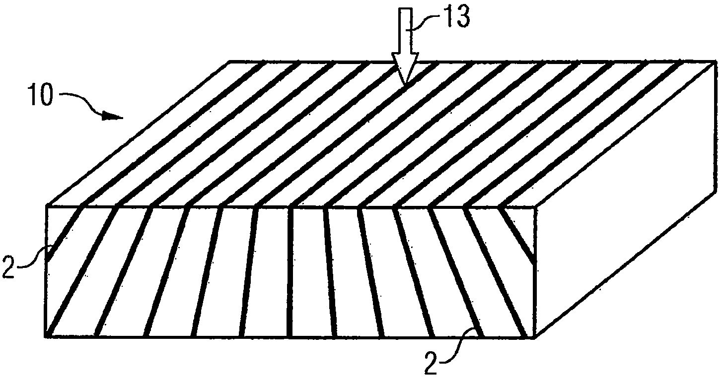
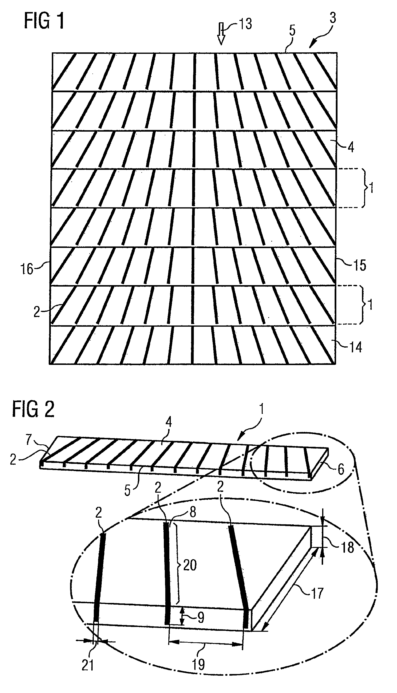
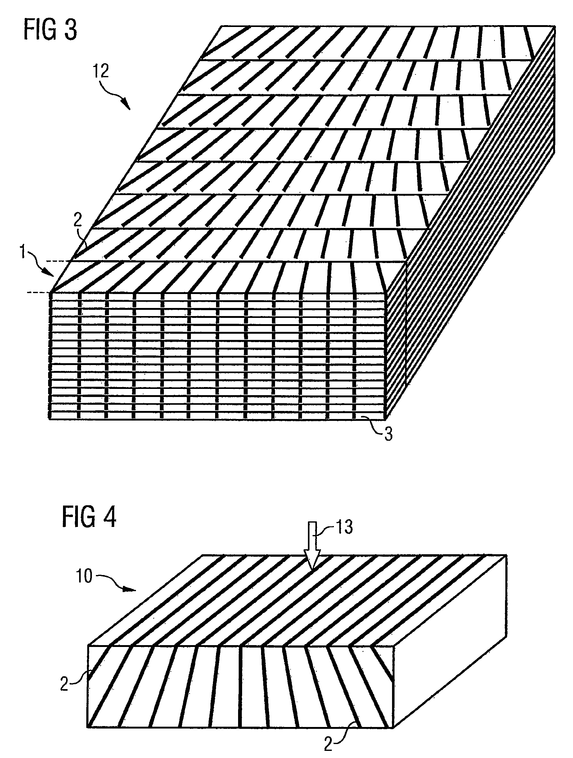
[0038]FIG. 1 shows a view from above a third element 3, for example, a plastic foil. Integrated into the plastic foil 3 are regularly-repeating second elements 2, such as microstructures. A number of second elements 2 form a first element 1. The second elements 2 are arranged in the radiation direction 13 with an angle 14 to the lateral edge 15 of the plastic foil 3. The angle 14 decreases continuously towards the middle of the plastic foil 3 or towards the middle of the first element 1 and then increases back to the second edge 16 again. A focus effect of an anti-scatter grid 10 formed therefrom in the direction of radiation 13, perpendicular to the width 5 of the third element 3, can be achieved.

[0039]The plastic foil 3 has, for example, a width of 400 mm and a thickness of between 0.1 and 0.5 mm

[0040]FIG. 2 shows a part of the third element 3 of one of the first elements 1, and a detailed view thereof. Located in the first element 1 are pits 8, in which the second elements 2 abso...


PUM


Abstract

An anti-scatter grid for medical x-ray devices is provided. The anti-scatter grid comprising a number of first elements from a first material with second elements made from a second material integrated therein. In this case the first material is more transparent to radiation than the second material. The second elements are arranged in the first elements such that for stacking of the first elements a grid absorbing scattered radiation is formed by means of second elements for radiation arriving perpendicular to the direction of the stacking of the first elements. The advantage of this is that this anti-scatter grid is able to be produced simply and reliably with a large aspect ratio.

Description

[0001]The present patent document claims the benefit of German Patent Application DE 10 2007 058 986.9 filed on Dec. 7, 2007, which is incorporated by reference.[0002]The present embodiments relate to an anti-scatter grid constructed from a number of elements.[0003]X-ray imaging technology imposes high demands on the image quality of the x-ray images. To produce images, such as images produced in medical diagnostics, an object to be examined is illuminated by x-ray radiation of an approximately point-type x-ray source and the distribution of the attenuation of the x-ray radiation is detected two-dimensionally on the side of the object opposite to the x-ray source. A row-by-row detection of the x-ray radiation attenuated by the object can be undertaken in computer tomography systems, for example. In addition to x-ray films and gas detectors, solid-state detectors are increasingly being used as x-ray detectors. The detectors generally have a matrix-type arrangement of optoelectronic s...

Claims


Application Information

Patent Timeline
Patent Type & Authority Patents(United States)
IPC IPC(8): G21K1/00G21K1/02
CPCG21K1/025A61B6/4258
Inventor KAMMEL, JOHANNAKOPPL, SEBASTIANORDUNG, MARCROAS, BERNHARDSTRATTNER, PETER
Owner SIEMENS HEALTHCARE GMBH
Why Eureka
Try Eureka