
High yield spray application

a spray application and composition technology, applied in the direction of chemical vapor deposition coating, special dispensing means, burners, etc., can solve the problems of accelerator tubing, difficult to achieve sufficient level of accuracy, and insufficient use of flow meters, etc., to achieve high yield spray application

Active Publication Date: 2010-11-30
GCP APPL TECH INC
View PDF20 Cites 9 Cited by
  • Summary
  • Abstract
  • Description
  • Claims
  • Application Information

AI Technical Summary

Benefits of technology

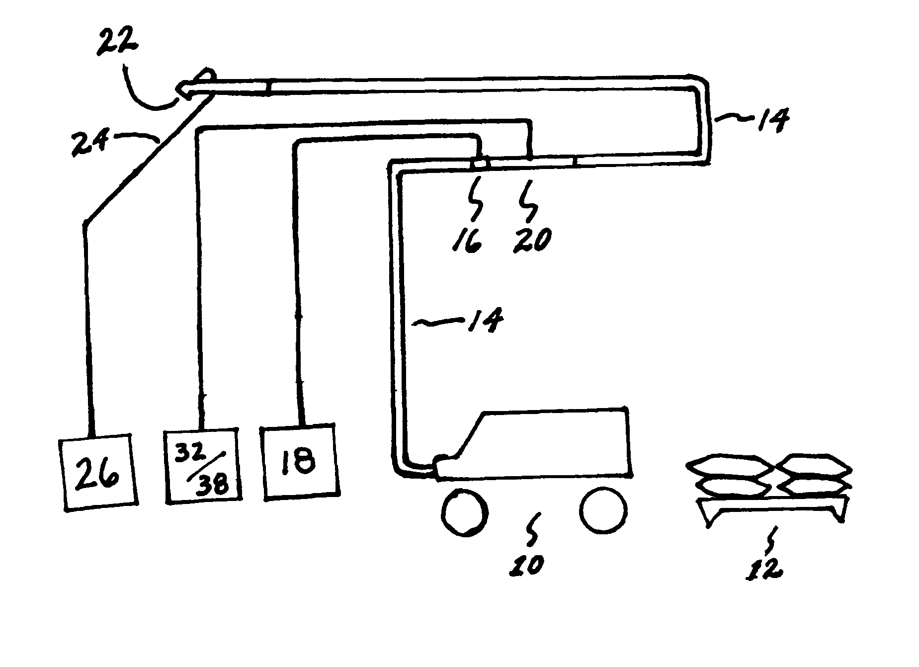
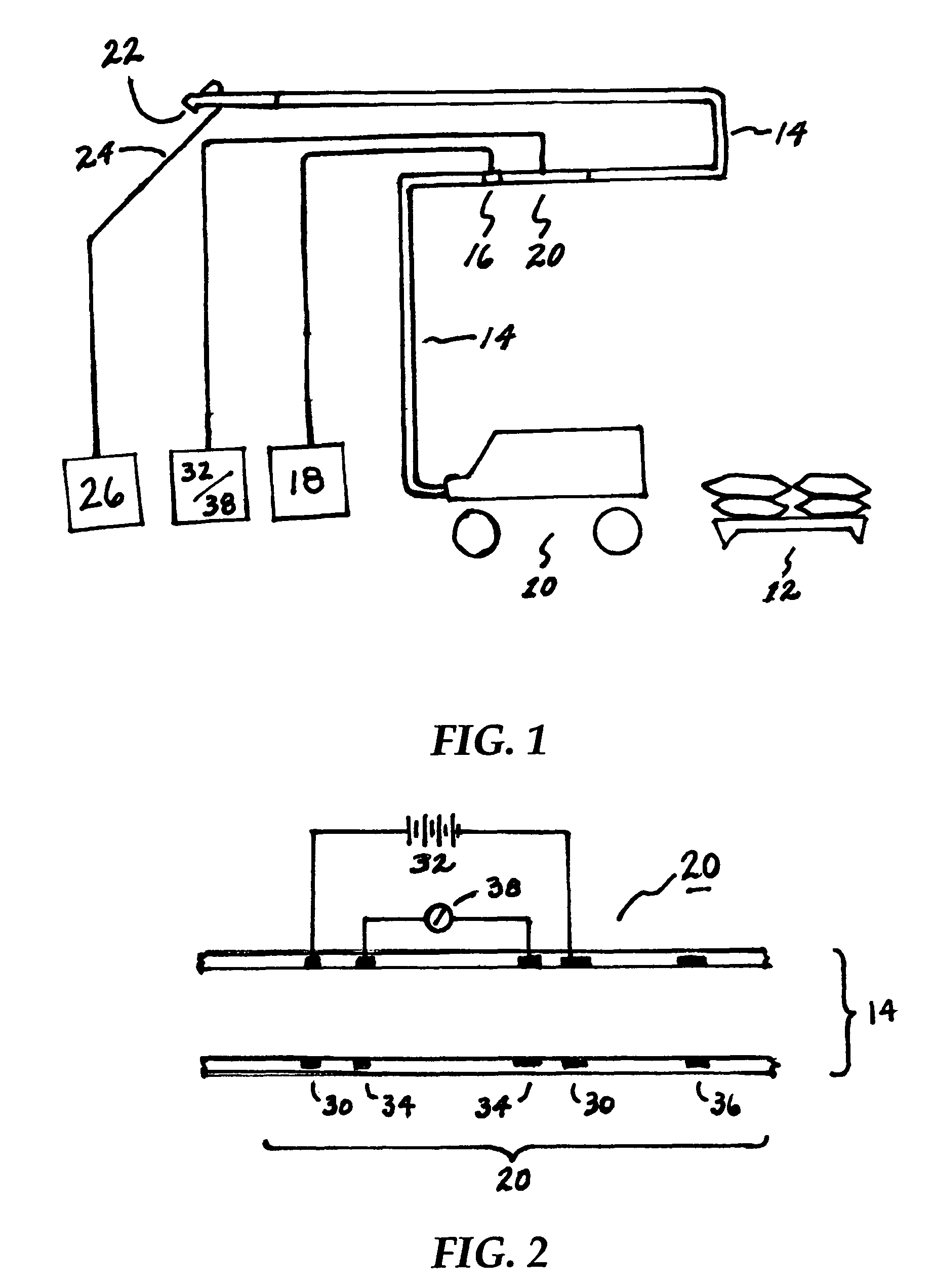
The present invention provides a method and device for achieving consistently high yield spray application of settable slurry compositions. This is achieved by monitoring and control of accelerator levels in the slurry, using a sensor that provides an indication of the actual levels within the hose or nozzle. This is much more accurate than prior art volumetric methods which merely monitor the flow rate of accelerator being pumped through the tubing on its way to the hose or nozzle. The invention is accurate, durable, convenient, and economical. The sensor can be housed in a rigid sleeve made of dielectric material, which can be screwed and / or clamped between hose sections, or incorporated directly into the nozzle. The invention allows for automatic or manual adjustment of accelerator injection rates into the slurry as conductivity measurements fall below or rise above a predetermined level. The technical effects of the invention are improved consistency and yield of spray applications.

Problems solved by technology

The present inventors, however, believe that the use of flow meters do not necessarily guarantee accurate monitoring where lengthy hoses are required for application of the slurry onto substrates.
A sufficient level of accuracy is especially harder to attain where the distances between the mixer and nozzle are great.
Typical obstacles for the accelerator tubing include door and wall openings, stairwells, and metal studs.
The tubing is susceptible to pinching, kinking, collapsing, leaking, and other conditions that prevent a controlled introduction of set accelerating agent into the slurry.

Method used


Image

  • High yield spray application
  • High yield spray application

Examples


Embodiment Construction

[0027]As used herein, the term “settable slurry composition” means and refers to compositions comprising an inorganic binder material, which, upon mixing with water, form a hydratable slurry that can be pumped through the length of a hose and spray-applied by nozzle onto a substrate.

[0028]The term “yield” means the volume of spray-applied slurry composition, after setting, per given weight of dry inorganic binder material used to prepare the settable slurry composition.

[0029]Typical inorganic binder materials contemplated for use in the settable slurry compositions include Plaster of Paris, stucco, gypsum, Portland cement, aluminous cement (e.g., a calcium sulphoaluminate cement, a high alumina cement), pozzolanic cement (e.g., finely ground blast furnace slag or fly ash, silica fume), gunite, magnesium oxychloride, magnesium oxysulfate, or mixtures thereof. Suitable settable slurry compositions are disclosed, for example, in U.S. Pat. No. 4,751,024 of Shu et al.; U.S. Pat. No. 4,90...


PUM

PropertyMeasurementUnit
distanceaaaaaaaaaa
distanceaaaaaaaaaa
setting timeaaaaaaaaaa

Abstract

Method and device for ensuring high yields during spraying of a settable slurry composition. The slurry is conveyed through a length of hose to a nozzle spray-orifice, and a set accelerator is introduced into the slurry at a distance “D” from the nozzle spray-orifice. The level of accelerator is monitored using a sensor located in the slurry path at a point after the set accelerator is injected. A preferred sensor comprises two pairs of conductivity sensors each having an annular body with a bore corresponding to the diameter of the hose or nozzle bore. Voltage of the slurry can be correlated to yields obtained when a salt-based accelerator fluid is injected into the slurry, such that levels of accelerator can be finely adjusted, and consistently high yields of spray coatings can be achieved.

Description

[0001]This application claims the benefit of U.S. Provisional Application No. 60 / 650,241 filed on Feb. 4, 2005.FIELD OF THE INVENTION[0002]The invention relates to spray application of rapid-setting compositions, and more particularly to a method and device for ensuring high yield spray application of a settable composition through accurate monitoring of the level of a set accelerating agent introduced into the spray composition.BACKGROUND OF THE INVENTION[0003]Spray applications are known which involve the use of an accelerating agent introduced into a composition after conveyance through a hose. In particular, the composition being pumped through the hose is a hydratable cementitious particle slurry or suspension which is expelled through a spray nozzle onto a substrate. For example, such accelerating agents are used in the spray-application of concrete (e.g., “shotcrete”) and fire protection coatings for metal substrates such as steel beams and panels.[0004]A particularly success...

Claims


Application Information

Patent Timeline
Patent Type & Authority Patents(United States)
IPC IPC(8): B05D1/00B05B12/00B05B12/08B05D1/02
CPCB05B12/004B05B12/1418B28C5/026C04B28/02C04B40/0028C04B40/0096E04F21/12C04B40/0032C04B7/02C04B28/14C04B28/06C04B38/02B28C7/024B05B7/32C04B2103/12C04B22/085C04B22/12C04B22/141C04B22/147C04B22/148C04B22/149C04B24/04C04B22/08Y02W30/91B05D1/02B05C5/00C23C16/52
Inventor ABBOTT, MICHAELHILTON, DENNIS M.LIPFORD, KEITHTAUB, KARL
Owner GCP APPL TECH INC
Learn More