Motor controller

a motor controller and controller technology, applied in the field of motor controllers, can solve problems such as preventing smooth movement, and achieve the effect of controlling the motor constant and stably, suppressing short-time oscillation

Inactive Publication Date: 2010-11-30
PANASONIC CORP
View PDF6 Cites 3 Cited by
  • Summary
  • Abstract
  • Description
  • Claims
  • Application Information

AI Technical Summary

Benefits of technology

[0016]With such a configuration, for example, even when a resonance frequency of the apparatus changes significantly in accordance with the load state, the notch control section controls the notch filter to change the notch width so as to attenuate a signal component of the original notch frequency and a signal component of the estimated oscillation frequency. Therefore, the motor controller of the present invention is capable of suppressing short-time oscillation, which occurs due to a significant change in resonance frequency of the apparatus, and is thus capable of constantly and stably controlling the motor.

Problems solved by technology

Therefore, in a case where a resonance frequency frequently changes due to a conditional change such as a positional change of the load, the oscillation and the notch frequency are modified every time a deviation occurs between the resonance frequency and the notch frequency, causing a problem of preventing smooth movement.

Method used


Image

  • Motor controller
  • Motor controller
  • Motor controller

Examples


first embodiment

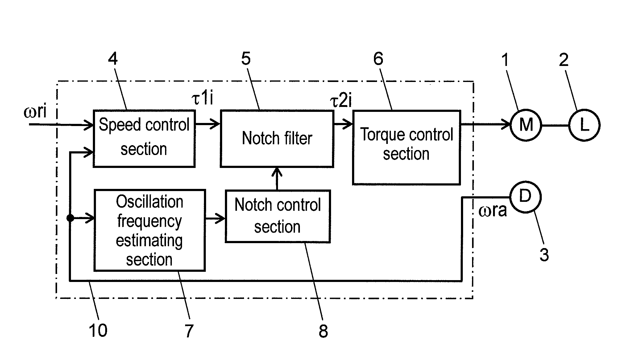
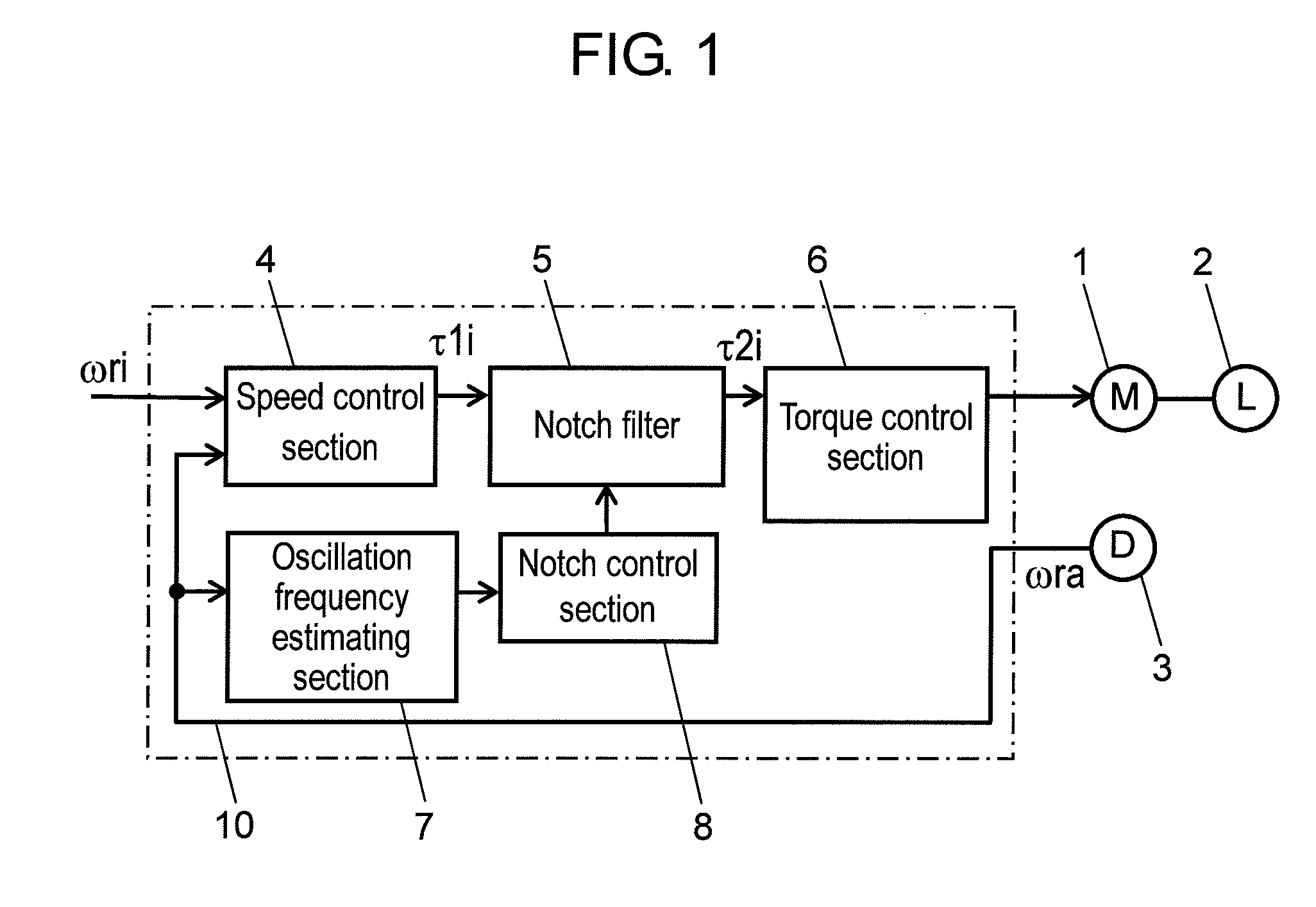
[0024]FIG. 1 is a block diagram of a motor controller according to a first embodiment of the present invention.

[0025]Motor controller 10 according to the first embodiment of the present invention is connected to motor 1 and speed detector 3. Motor 1 is connected with load 2. Further, speed detector 3 measures a rotational speed of a moving element (not shown) provided inside motor 1, and outputs speed detection signal ωra showing a speed amount in accordance with the rotational speed. It is to be noted that in the present embodiment, a description is given by taking an example of speed detector 3 detecting an amount of rotational speed of the moving element as a moving amount of moving section of motor 1 as described above.

[0026]As shown in FIG. 1, motor controller 10 includes speed control section 4, notch filter 5, oscillation frequency estimating section 7, notch control section 8, and torque control section 6.

[0027]Speed command signal ωri showing a speed command value and speed...

second embodiment

[0056]In the following, motor controller 20 according to a second embodiment of the present invention is described with reference to drawings.

[0057]FIG. 4 is a block diagram of motor controller 20 according to the second embodiment of the present invention.

[0058]In FIG. 4, the same constituents as those of motor controller 10 according to the first embodiment are provided with the same numerals, and detailed descriptions thereof are omitted.

[0059]In comparison with the first embodiment, motor controller 20 includes a plurality of notch filters 5, and also includes notch control section 80 that controls these notch filters 5. Notch control section 80 is capable of changing a notch frequency and a notch width of each of the plurality of notch filters 5. Further, notch control section 80 is capable of switching the state of the plurality of notch filters 5 between the valid state and the invalid state. It is to be noted that in the present embodiment, as shown in FIG. 4, a description ...


PUM


Abstract

A motor controller includes: a notch filter arranged inside a control system; an oscillation frequency estimating section which estimates an oscillation frequency component in a motor; and a notch control section which controls a notch filter so as to change a notch frequency and a notch width. The notch control section changes a frequency between an oscillation frequency and a notch frequency set in a notch filter as a new notch frequency, while changing a notch width to a new notch width such that the notch width is larger after the change than before the change.

Description

FIELD OF THE INVENTION[0001]The present invention relates to a motor controller for controlling a speed or a position of a motor as well as a load driven by the motor. The present invention particularly relates to a motor controller for suppressing mechanical resonance that occurs in the case of driving the load.BACKGROUND OF THE INVENTION[0002]Such a conventional motor controller for suppressing mechanical resonance is disclosed, for example, in Unexamined Japanese Patent Publication No. 2003-52188.[0003]In the following, the conventional motor controller is described with reference to FIG. 6. FIG. 6 is a block diagram showing a system configuration of the conventional motor controller.[0004]This conventional motor controller 100 is connected to motor 101 and speed detector 103. Motor 101 is connected with load 102. Further, speed detector 103 measures a speed of motor 101, and outputs speed detection signal ωra of motor 101.[0005]As shown in FIG. 6, motor controller 100 includes s...

Claims


Application Information

Patent Timeline
Patent Type & Authority Patents(United States)
IPC IPC(8): G05B5/01G05B13/02H02P25/098H02P29/00
CPCH02P23/04
Inventor TAZAWA, TORU
Owner PANASONIC CORP
Why Eureka
Try Eureka