High linearity frequency conversion system and method

a frequency conversion system and high linearity technology, applied in the field of mixing signals, can solve the problems of poor linearity performance inability to provide the dynamic ranges required by some systems, and linearity of many conventional frequency converters, so as to reduce rise and fall times

Active Publication Date: 2010-11-30
NORTHROP GRUMMAN SYST CORP
View PDF27 Cites 5 Cited by
  • Summary
  • Abstract
  • Description
  • Claims
  • Application Information

AI Technical Summary

Benefits of technology

[0008]Accordingly, the present invention provides a frequency conversion circuit and method that experiences high-linearity performance over a wide range of frequencies.
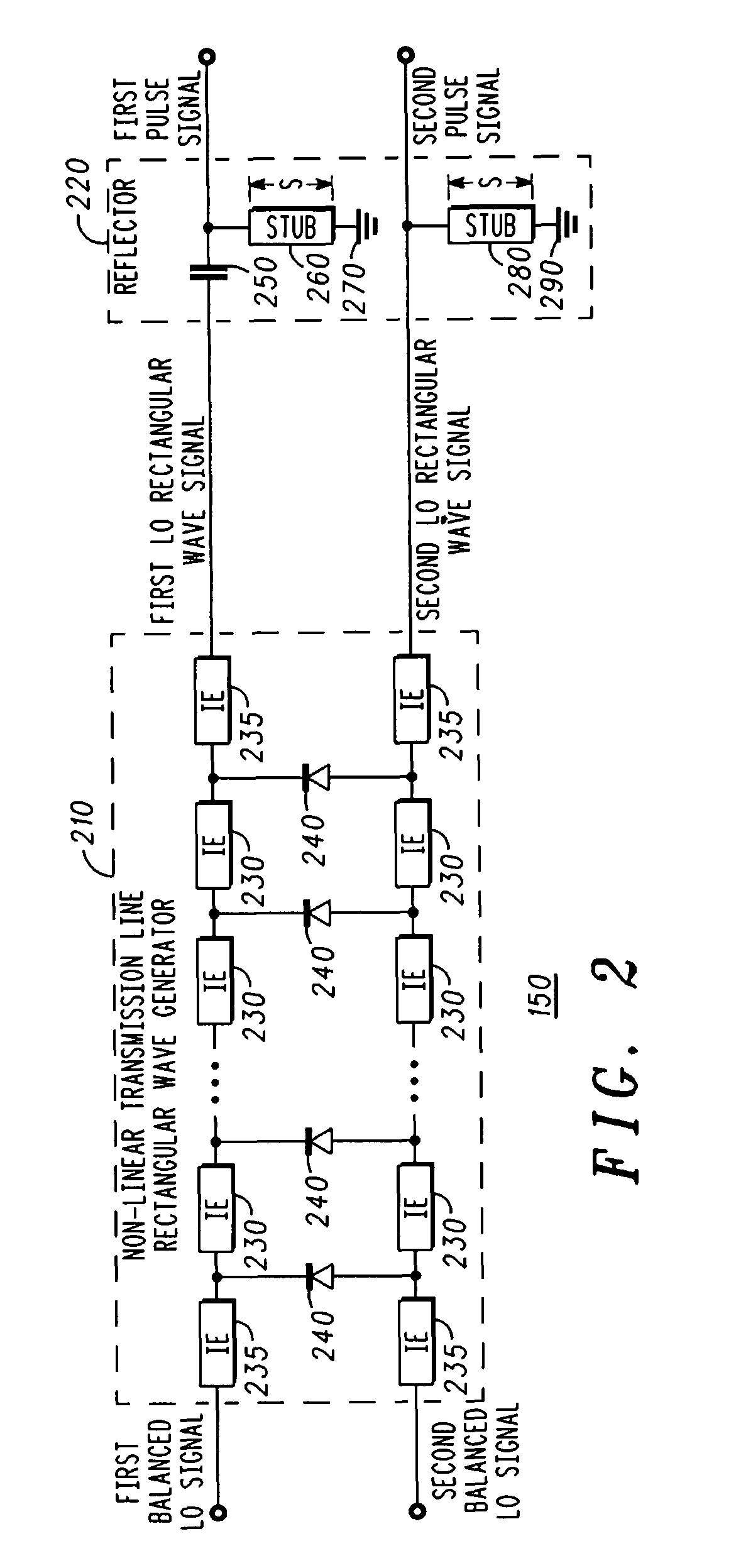
[0013]The pulse generator may comprise: a rectangular wave generator configured to receive the balanced local oscillator signal pair, and to generate a balanced rectangular wave signal pair having the reference frequency; and a reflector configured to delay and reflect the balanced rectangular wave signal pair to provide an inverted rectangular wave signal pair. In this case, the balanced rectangular pulse signal pair may be formed by a sum of the balanced rectangular wave signal pair and the inverted rectangular wave signal pair, and a width of the balanced rectangular pulse signal pair may be determined by a length of the delay. The reflection and delay process reduces the rise time and fall time of the pulse. The reflector may be a pair of shorted stubs.
[0022]The generating of the balanced pulse signal pair may further comprise: converting the balanced local oscillator signal pair into a balanced rectangular wave signal pair having the reference frequency; delaying and reflecting the balanced rectangular wave signal pair to generate an inverted rectangular wave signal pair having reduced rise times and fall times; and combining the balanced rectangular wave signal pair and the inverted rectangular wave signal pair to form the balanced rectangular pulse signal pair.

Problems solved by technology

One limitation for meeting this high dynamic range requirement is the linearity of conventional frequency converters, i.e., the range for which the conventional frequency converters operate in a linear manner.
Many conventional frequency converters have poor linearity performance in that they cannot provide the dynamic ranges required by some systems.
This results in intermodulation distortion (IMD) and spurious responses, indicating that the star mixer has a relatively small range of linear operation.

Method used


Image

  • High linearity frequency conversion system and method
  • High linearity frequency conversion system and method
  • High linearity frequency conversion system and method

Examples


Embodiment Construction

[0031]The instant disclosure is provided to further explain in an enabling fashion the best modes of performing one or more embodiments of the present invention. The disclosure is further offered to enhance an understanding and appreciation for the inventive principles and advantages thereof, rather than to limit in any manner the invention. The invention is defined solely by the appended claims including any amendments made during the pendency of this application and all equivalents of those claims as issued.

[0032]It is further understood that the use of relational terms such as first and second, and the like, if any, are used solely to distinguish one from another entity, item, or action without necessarily requiring or implying any actual such relationship or order between such entities, items or actions. It is noted that some embodiments may include a plurality of processes or steps, which can be performed in any order, unless expressly and necessarily limited to a particular or...


PUM


Abstract

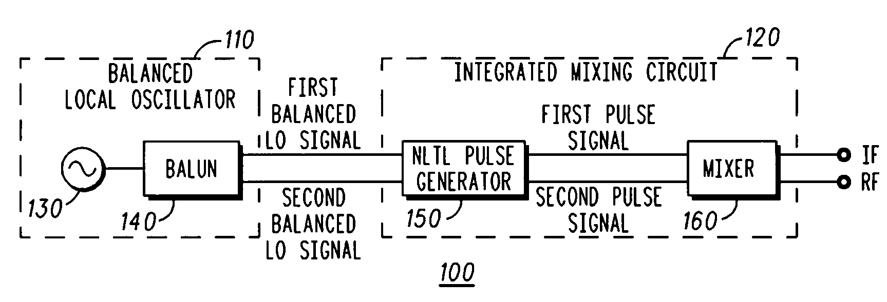
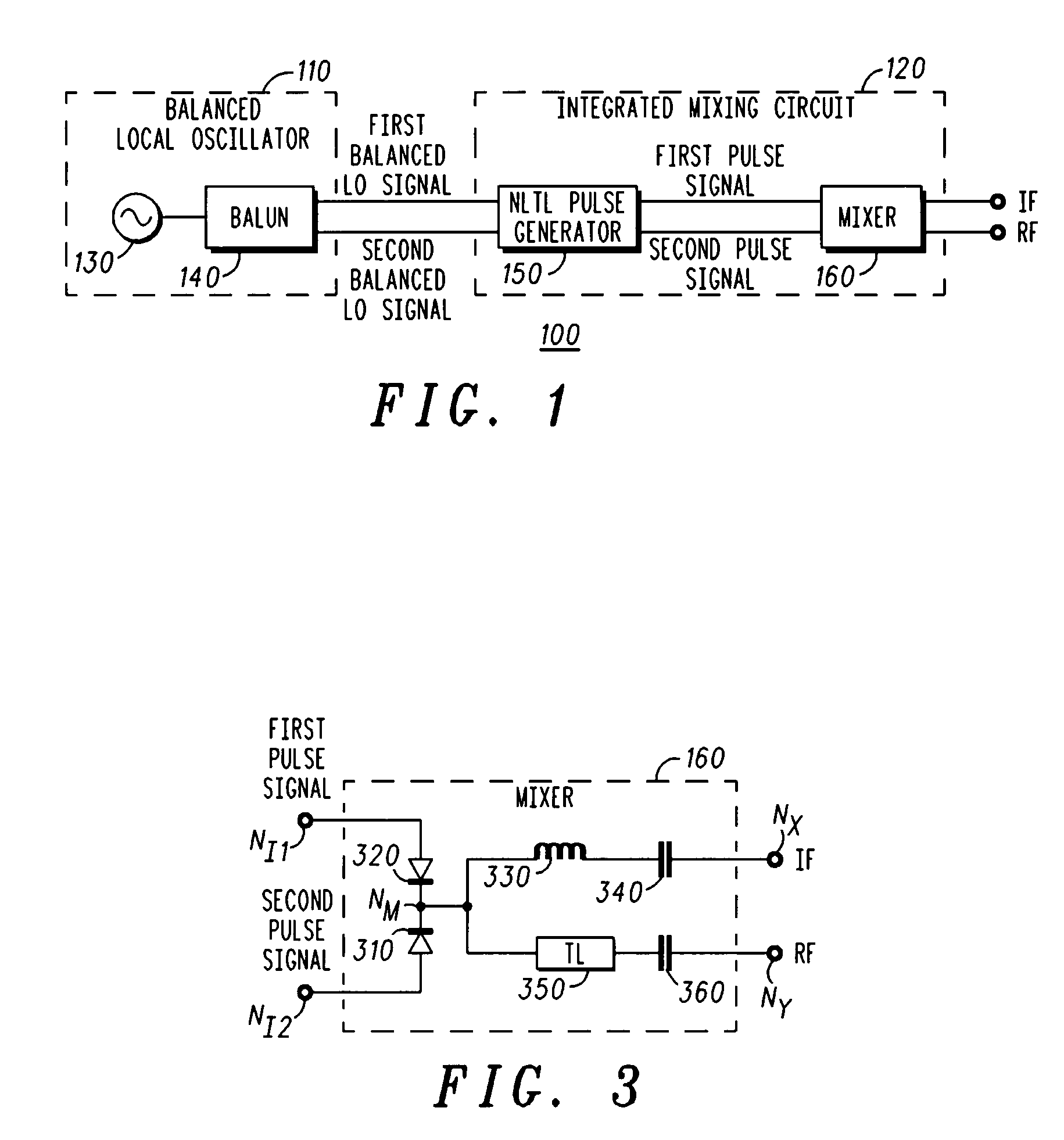
A frequency converter (100) is provided, comprising: a pulse generator (150) configured to receive a balanced local oscillator signal pair and to generate a balanced rectangular pulse signal pair having the reference frequency; and a mixer (160) configured to mix an input signal having an input frequency with the balanced rectangular pulse signal pair to generate an output signal having an output frequency. The input frequency is different from the output frequency, and the pulse generator and the mixer are formed on a single integrated circuit (120). The frequency converter may comprise a balanced local oscillator (110) configured to generate the balanced local oscillator signal pair. The balanced local oscillator may comprise: an unbalanced local oscillator (130) configured to provide an unbalanced local oscillator signal having the reference frequency; and a balun (140) configured to generate the balanced local oscillator signal pair based on the unbalanced local oscillator signal.

Description

FIELD OF THE INVENTION[0001]The present invention relates generally to the mixing of signals, and more particularly to a high linearity system and method for mixing an intermediate frequency (IF) signal to get a radio frequency (RF) signal or mixing an RF signal to get an IF signal.BACKGROUND[0002]Many signal processing and radio telecommunications systems make use of both radio frequencies (RF) and intermediate frequencies (IF) during operation. For example, AM and FM radio use an RF data signal with an IF carrier signal. In addition, some radar or microwave telecommunications applications also make use of RF and IF signals. In such devices a higher-frequency RF signal is transmitted over the air, while a lower-frequency IF signal is used for modulation / demodulation within transmitter and receiver circuitry.[0003]Conversion between RF and typically takes place in a frequency converter that receives as its inputs a local oscillator (LO) signal and a signal for conversion (i.e., one ...

Claims


Application Information

Patent Timeline
Patent Type & Authority Patents(United States)
IPC IPC(8): H04B1/26H04B15/00
CPCH03D7/1408H04B1/28
Inventor KINTIS, MARKFONG, FLAVIA S.MAAS, STEVE
Owner NORTHROP GRUMMAN SYST CORP
Why Eureka
Try Eureka