

Imaging lens assembly
a technology of imaging lens and assembly, which is applied in the field of imaging lens assembly, can solve the problems of effective reduction of the sensitivity of the imaging lens assembly, and achieve the effects of facilitating the enlargement of the field of view, reducing the total track length of the imaging lens assembly, and improving image quality
- Summary
- Abstract
- Description
- Claims
- Application Information
AI Technical Summary
Benefits of technology
Problems solved by technology
Method used
Image

Examples
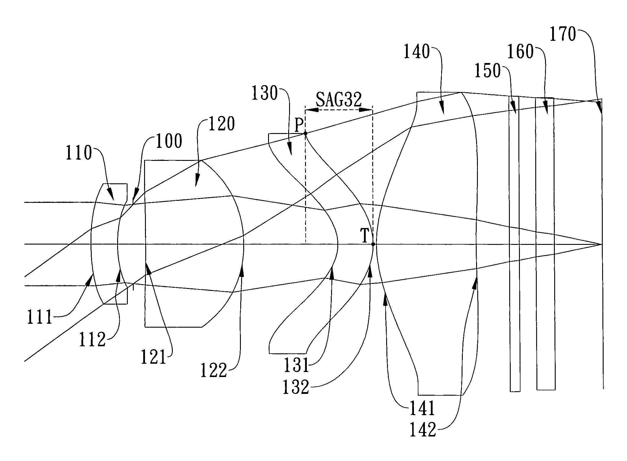
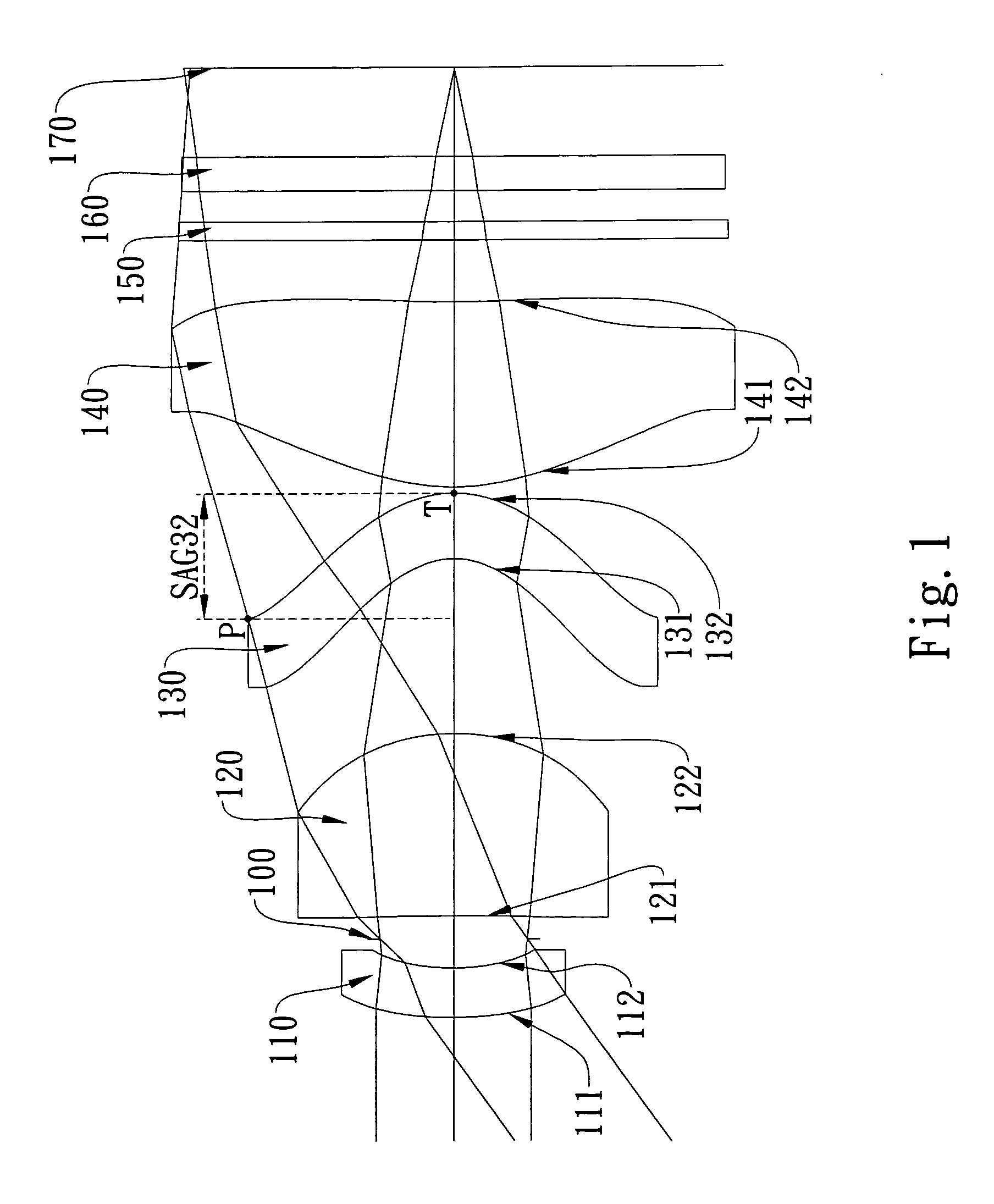
first embodiment
[0068]In the present imaging lens assembly, the focal length of the imaging lens assembly is f, and it satisfies the relation: f=6.02 (mm).
[0069]In the first embodiment of the present imaging lens assembly, the f-number of the imaging lens assembly is Fno, and it satisfies the relation: Fno=2.45.
[0070]In the first embodiment of the present imaging lens assembly, half of the field of view of the imaging lens assembly is HFOV, and it satisfies the relation: HFOV=35.2 (degrees).
[0071]In the first embodiment of the present imaging lens assembly, the Abbe number of the second lens element 120 is V2, the Abbe number of the third lens element 130 is V3, and they satisfy the relation: V2−V3=26.6.
[0072]In the first embodiment of the present imaging lens assembly, the focal length of the imaging lens assembly is f, the focal length of the first lens element 110 is f1, and they satisfy the relation: f / f1=−0.30.
[0073]In the first embodiment of the present imaging lens assembly, the focal length...
second embodiment
[0086]In the present imaging lens assembly, the focal length of the imaging lens assembly is f, and it satisfies the relation: f=5.83 (mm).
[0087]In the second embodiment of the present imaging lens assembly, the f-number of the imaging lens assembly is Fno, and it satisfies the relation: Fno=2.80.
[0088]In the second embodiment of the present imaging lens assembly, half of the field of view of the imaging lens assembly is HFOV, and it satisfies the relation: HFOV=31.1 (degrees).
[0089]In the second embodiment of the present imaging lens assembly, the Abbe number of the second lens element 320 is V2, the Abbe number of the third lens element 330 is V3, and they satisfy the relation: V2−V3=32.5.
[0090]In the second embodiment of the present imaging lens assembly, the focal length of the imaging lens assembly is f, the focal length of the first lens element 310 is f1, and they satisfy the relation: f / f1=−0.16.
[0091]In the second embodiment of the present imaging lens assembly, the focal l...
third embodiment
[0104]In the present imaging lens assembly, the focal length of the imaging lens assembly is f, and it satisfies the relation: f=6.55 (mm).
[0105]In the third embodiment of the present imaging lens assembly, the f-number of the imaging lens assembly is Fno, and it satisfies the relation: Fno=2.80.
[0106]In the third embodiment of the present imaging lens assembly, half of the field of view of the imaging lens assembly is HFOV, and it satisfies the relation: HFOV=28.1 (degrees).
[0107]In the third embodiment of the present imaging lens assembly, the Abbe number of the second lens element 520 is V2, the Abbe number of the third lens element 530 is V3, and they satisfy the relation: V2−V3=32.5.
[0108]In the third embodiment of the present imaging lens assembly, the focal length of the imaging lens assembly is f, the focal length of the first lens element 510 is f1, and they satisfy the relation: f / f1=−0.45.
[0109]In the third embodiment of the present imaging lens assembly, the focal length...
PUM
 Abstract
Description
Claims
Application Information