
CMOS inverter layout for increasing effective channel length

Active Publication Date: 2010-12-07
SAMSUNG ELECTRONICS CO LTD
View PDF4 Cites 4 Cited by
  • Summary
  • Abstract
  • Description
  • Claims
  • Application Information

AI Technical Summary

Benefits of technology

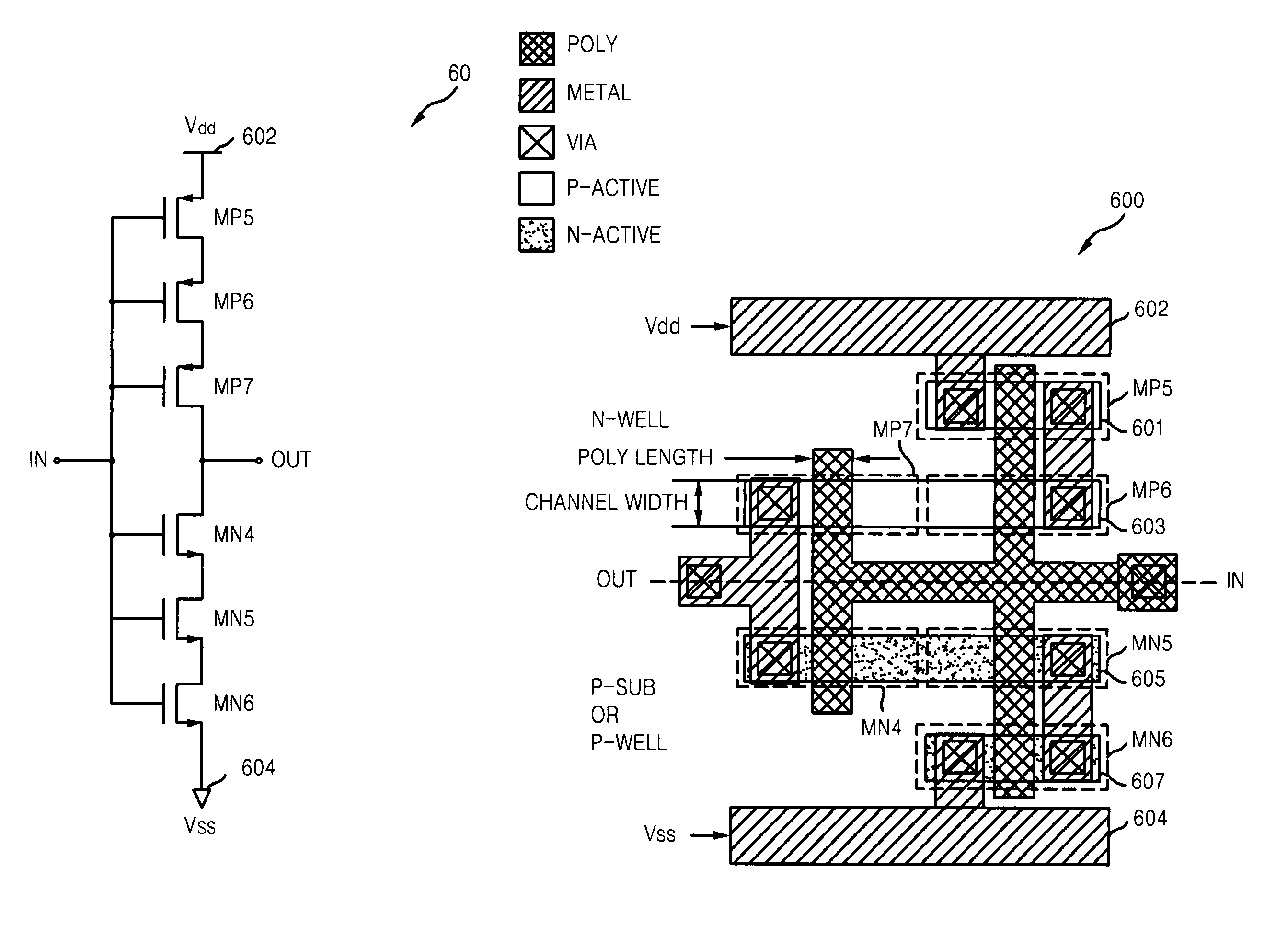
[0015]Example embodiments provide a layout of a complementary metal oxide semiconductor (CMOS) inverter having a longer delay than a conventional CMOS inverter by increasing an effective channel length while setting a poly length to the minimum feature size.

Problems solved by technology

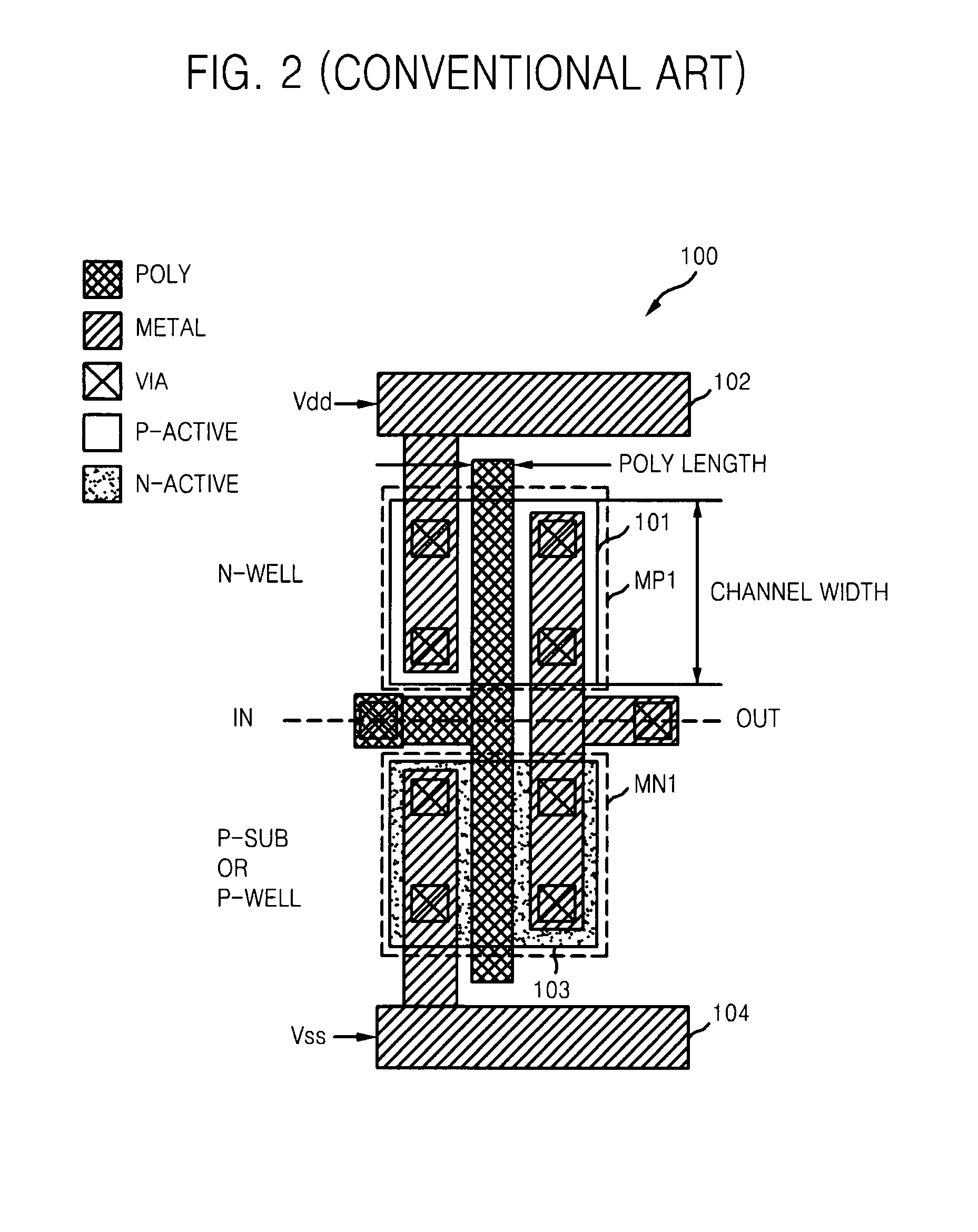
However, in conventional devices including a first type of circuit requiring a longer and a second type of circuit requiring a shorter delay, difficulties arise when attempting to align the polies of the first type of circuit and the second type of circuit at regular intervals.
Conventionally, if an integrated circuit includes a first type of circuit having an first poly length and a second type of circuit having different poly length, it is difficult, complex and / or expensive to align the polies at regular intervals.
For example, if polies having different poly lengths are aligned at regular intervals in an integrated circuit, poly pitch of the integrated circuit is not uniform.
In the alternative, if the poly pitch is uniform in an integrated circuit having polies with at least two different poly lengths, the poly intervals are not uniform.
In light of the above-identified difficulties, costs, process variations and layout areas for an integrated circuit may increase.

Method used


Image

  • CMOS inverter layout for increasing effective channel length
  • CMOS inverter layout for increasing effective channel length
  • CMOS inverter layout for increasing effective channel length

Examples


Embodiment Construction

[0030]Example embodiments will now be described more fully with reference to the accompanying drawings, in which example embodiments are shown. Example embodiments may, however, be embodied in many different forms and should not be construed as being limited to the embodiments set forth herein. Rather, these embodiments are provided so that this disclosure will be thorough and complete, and will fully convey the scope of the example embodiments to those skilled in the art.

[0031]It will be understood that when an element or layer is referred to as being “on,”“connected to” or “coupled to” another element or layer, it can be directly on, connected or coupled to the other element or layer or intervening elements or layers may be present. In contrast, when an element is referred to as being “directly on,”“directly connected to” or “directly coupled to” another element or layer, there are no intervening elements or layers present. Like reference numerals refer to like elements throughout...


PUM


Abstract

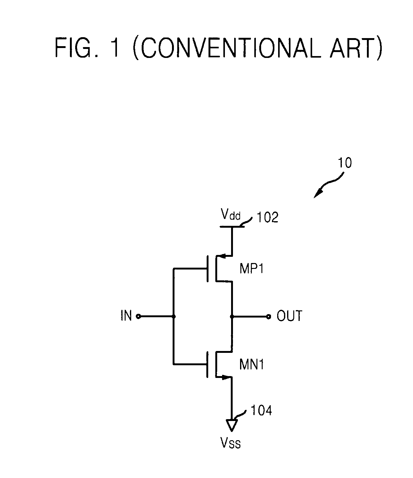
Provided is a complementary metal oxide semiconductor (CMOS) inverter layout for increasing an effective channel length. The CMOS inverter layout may include first and second conductive MOS transistors respectively formed in first and second active regions, metal lines electrically connecting the first and second conductive MOS transistors, and one or more gate electrodes electrically connecting the gates of the first and second conductive MOS transistors. The widths of one or more gate electrodes may be set to a reduced and / or minimum feature size to reduce and / or minimize a process variation and a layout area of the CMOS inverter. Also, the first and second conductive MOS transistors may be connected in series via the metal lines to increase an effective channel length, thereby realizing a layout of the CMOS inverter having a longer delay than a conventional CMOS inverter.

Description

PRIORITY STATEMENT[0001]This application claims priority under 35 U.S.C. §119 from Korean Patent Application No. 10-2006-0032140, filed on Apr. 10, 2006, the entire contents of which is hereby incorporated by reference.BACKGROUND[0002]1. Field[0003]Example embodiments relate to layouts of a complementary metal oxide semiconductor (CMOS) inverters. More particularly, example embodiments relate to layouts of CMOS inverters, in which the width of a gate electrode has a minimum feature size, as defined below in this application, and an effective channel length is increased to have a longer delay than conventional inverters.[0004]2. Description of the Related Art[0005]As used herein, the terms “minimum feature size” denote a dimension of the smallest feature actually constructed in a semiconductor manufacturing process. Because chipmakers continually seek to provide more circuitry into the same amount of space, there is a general desire to continue reducing the minimum feature size.[0006...

Claims


Application Information

Patent Timeline
IPC IPC(8): G06F17/50
CPCH01L27/0207H01L27/092H01L21/8238
Inventor KIM, MIN-SU
Owner SAMSUNG ELECTRONICS CO LTD
Learn More