Assembling an annular combustion chamber of a turbomachine

a combustion chamber and annular technology, applied in the direction of machines/engines, mechanical equipment, lighting and heating apparatus, etc., can solve the problems of reducing the lifetime reducing the efficiency of the combustion chamber, and presenting relatively low strength, so as to achieve effective damping of vibration and mitigate the effect of such drawbacks

Active Publication Date: 2010-12-14
SN DETUDE & DE CONSTR DE MOTEURS DAVIATION S N E C M A
View PDF8 Cites 30 Cited by
  • Summary
  • Abstract
  • Description
  • Claims
  • Application Information

AI Technical Summary

Benefits of technology

[0006]The present invention thus seeks mainly to mitigate such drawbacks by proposing an assembly system making it possible in operation to achieve free expansion of the chamber end wall relative to the axial walls, while providing effective damping of the vibration to which the chamber end wall is subjected.
[0008]The presence of fastener tabs that are flexible but prestressed, in combination with fastener systems presenting a determined amount of radial clearance between the nut and the axial wall, has the effect of simultaneously improving the damping of the vibration to which the combustion chamber is subjected, and of attenuating the effects of the expansion in operation of the chamber end wall relative to the axial walls. As a result, the fastener tabs are subjected in operation to small amounts of bending stress only.
[0009]In an advantageous disposition of the invention, each fastener tab includes a washer of metal with the corresponding slideway bushing and fastener bolt passing therethrough, the bushing being made of metal. Contact between the bushing and the fastener tab is of the metal-on-metal type. Such contact presents the advantage of leading to much less wear, and to repairs that are limited in cost compared with repairing a worn contact of ceramic-on-metal type.
[0010]In another advantageous disposition of the invention, contact between the washer of a fastener tab and the corresponding slideway bushing is substantially toroidal. This type of contact has the advantage of facilitating sliding between the bushing and the fastener tab, while avoiding the phenomenon of jamming.
[0011]In yet another advantageous disposition of the invention, the washer of each fastener tab presents greater thickness so as to increase the contact area between said washer and the corresponding slideway bushing. Contact forces are thus spread over a larger area, thereby reducing contact wear between the bushing and the fastener tab.
[0012]Preferably, each fastener tab presents the same assembly prestress so as to impart stiffness to the chamber end wall for dynamic stability, during an initial operation stage.

Problems solved by technology

The use of a combustion chamber that is made entirely out of metal is completely unsuitable from a thermal point of view because of the very high temperatures of the combustion gases.
This reduces the lifetime of the combustion chamber.
However, composite materials are very expensive and present relatively low strength when faced with high levels of mechanical stress.
Thus, use of such materials is usually limited to the axial walls of the combustion chamber, while the radial wall (i.e. the end wall of the chamber) that unites these axial walls at their upstream ends continues to be made more conventionally out of metal.
Unfortunately, metals and composite materials present coefficients of thermal expansion that are very different.
This leads to problems in the systems for assembling the combustion chamber between the axial walls that are made of composite material and the chamber end wall that is made of metal.
In particular, the use of conventional bolt systems is no longer possible from the point of view of the mechanical strength of the walls.
In particular, such an assembly system does not make it possible to provide expansion that is sufficiently free, while also providing effective damping of the vibration to which the chamber end wall is subjected in operation.
As a result, the fastener tabs are subjected in operation to very high levels of bending stress that are particularly harmful to the mechanical strength of the assembly, and in particular to the strength of the composite.

Method used


Image

  • Assembling an annular combustion chamber of a turbomachine
  • Assembling an annular combustion chamber of a turbomachine
  • Assembling an annular combustion chamber of a turbomachine

Examples


Embodiment Construction

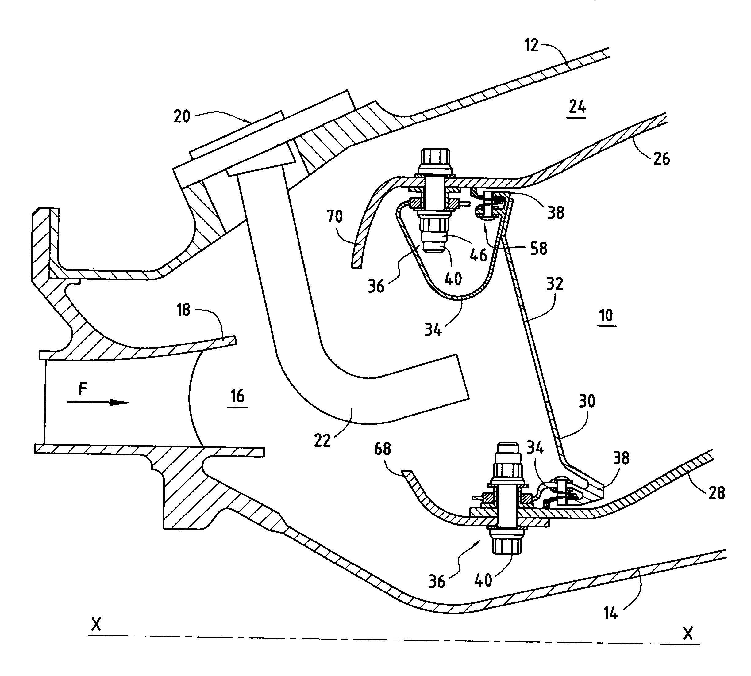
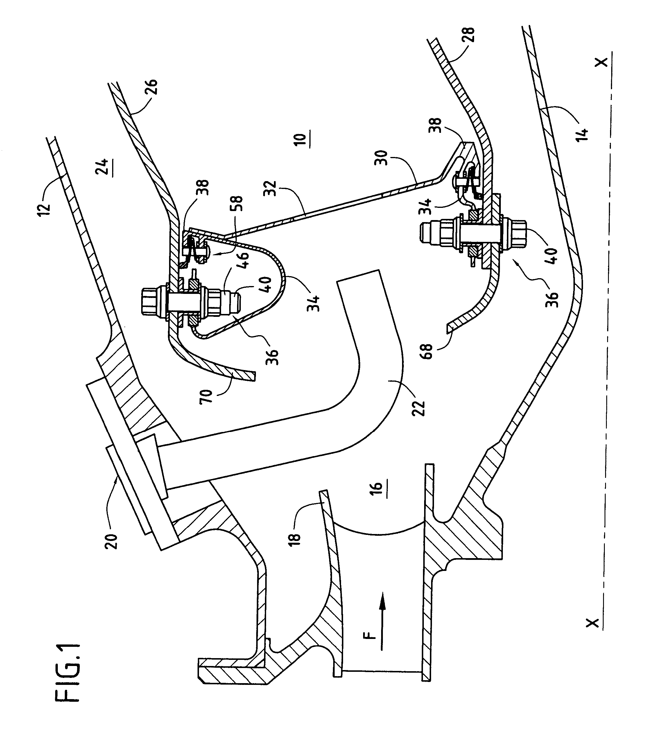
[0022]FIG. 1 is a fragmentary axial section view of a turbomachine combustion chamber 10 in its environment.

[0023]An outer annular shroud (or outer casing) 12 and an inner annular shroud (or inner casing) 14 coaxial therewith are centered on the axis X-X of the turbomachine. An annular space 16 formed between these two shrouds receives compressed air in a general stream F coming from a compressor (not shown) of the turbomachine via an annular diffusion duct 18. This air is for combustion of the fuel in the chamber 10.

[0024]A plurality of injection systems 20 are distributed regularly around the diffusion duct 18 and open out into the annular space 16. Each of these injection systems is provided with a fuel injection nozzle 22 secured to the outer shroud 12. In order to simplify the drawings, the mixer and the deflector associated with each injection nozzle are omitted.

[0025]The combustion chamber 10 of the turbomachine is mounted inside the annular space 16 so as to leave respective...


PUM


Abstract

An annular combustion chamber comprising axial walls interconnected by a chamber end wall having a coefficient of thermal expansion that is different from that of the axial walls, the chamber end wall being provided with a plurality of inner and outer fastener tabs secured by fastener systems to the end portions of the axial walls. Each fastener system comprises a bolt, a nut tightened onto one of the ends of the bolt, and a slideway bushing disposed around the bolt between the nut and the end portion of the corresponding axial wall, a determined amount of radial clearance being provided between the nut and the end portion of the axial wall so as to enable the chamber end wall to expand radially freely in operation relative to the axial walls.

Description

BACKGROUND OF THE INVENTION[0001]The present invention relates to the general field of combustion chambers for turbomachines. It relates more particularly to the problem posed by assembling an annular combustion chamber in which the axial walls and the end wall of the chamber are made out of materials having coefficients of thermal expansion that are different.[0002]In the field of aviation, it is becoming more and more widespread to use high-temperature composite materials of the ceramic matrix composite (CMC) type instead of metals when making various components of a turbomachine, and in particular its combustion chamber. The use of a combustion chamber that is made entirely out of metal is completely unsuitable from a thermal point of view because of the very high temperatures of the combustion gases. This reduces the lifetime of the combustion chamber.[0003]However, composite materials are very expensive and present relatively low strength when faced with high levels of mechanic...

Claims


Application Information

Patent Timeline
Patent Type & Authority Patents(United States)
IPC IPC(8): F02C3/06
CPCF23R3/007F23R3/60
Inventor DE SOUSA, MARIO CESARHERNANDEZ, DIDIER HIPPOLYTEMARNAS, LAURENT PIERRE ELYSEE GASTON
Owner SN DETUDE & DE CONSTR DE MOTEURS DAVIATION S N E C M A
Why Eureka
Try Eureka