
Marine J-lay pipelaying system

Active Publication Date: 2010-12-14
ITREC BV
View PDF13 Cites 2 Cited by
  • Summary
  • Abstract
  • Description
  • Claims
  • Application Information

AI Technical Summary

Benefits of technology

[0004]The present invention aims to provide an improved marine J-lay pipelaying system for use on a vessel. It is an object of the present invention to allow for low pipeline stresses during laying of the pipeline, even when the vessel is comparatively small and thus subject to relatively large sea-state induced motions. It is a further object of the present invention to provide an efficient pipelaying system. It is a further object of the present invention to provide for an efficient and reliable loading of new pipe sections into the J-lay tower. It is a further object of the present invention to provide for a new pipe section loader to be used for J-lay pipelaying systems.SUMMARY OF THE INVENTION
[0008]It is noted that the present invention e.g. also includes designs wherein the J-lay tower can—as an option—be brought in a fixed orientation mode, e.g. by arresting the J-lay tower in a desired orientation with respect to the vessel. Also it can be envisaged that damping means are provided to dampen the pivotal motions of the J-lay tower in the freely pivotal mode. Also, as an alternative embodiment, the J-lay tower could be arranged to be gimballed with respect to the vessel such that a pivotal motion is allowed in any direction, so that the J-lay tower has two degrees of angular freedom.

Problems solved by technology

This is hard to do, if at all, and dangerous, as any operator mistake will result in a collision between the loader and the swaying J-lay tower.

Method used


Image

  • Marine J-lay pipelaying system
  • Marine J-lay pipelaying system
  • Marine J-lay pipelaying system

Examples


Embodiment Construction

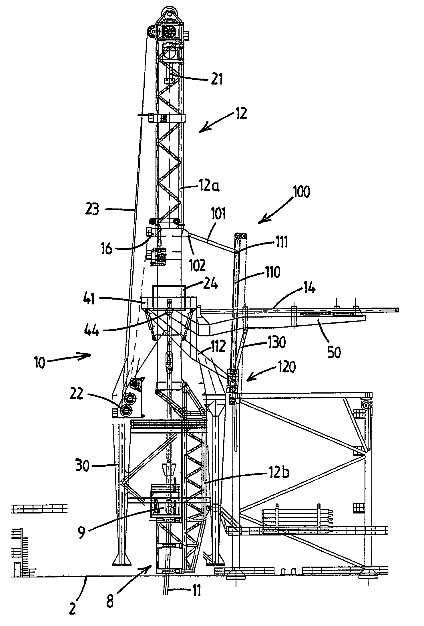
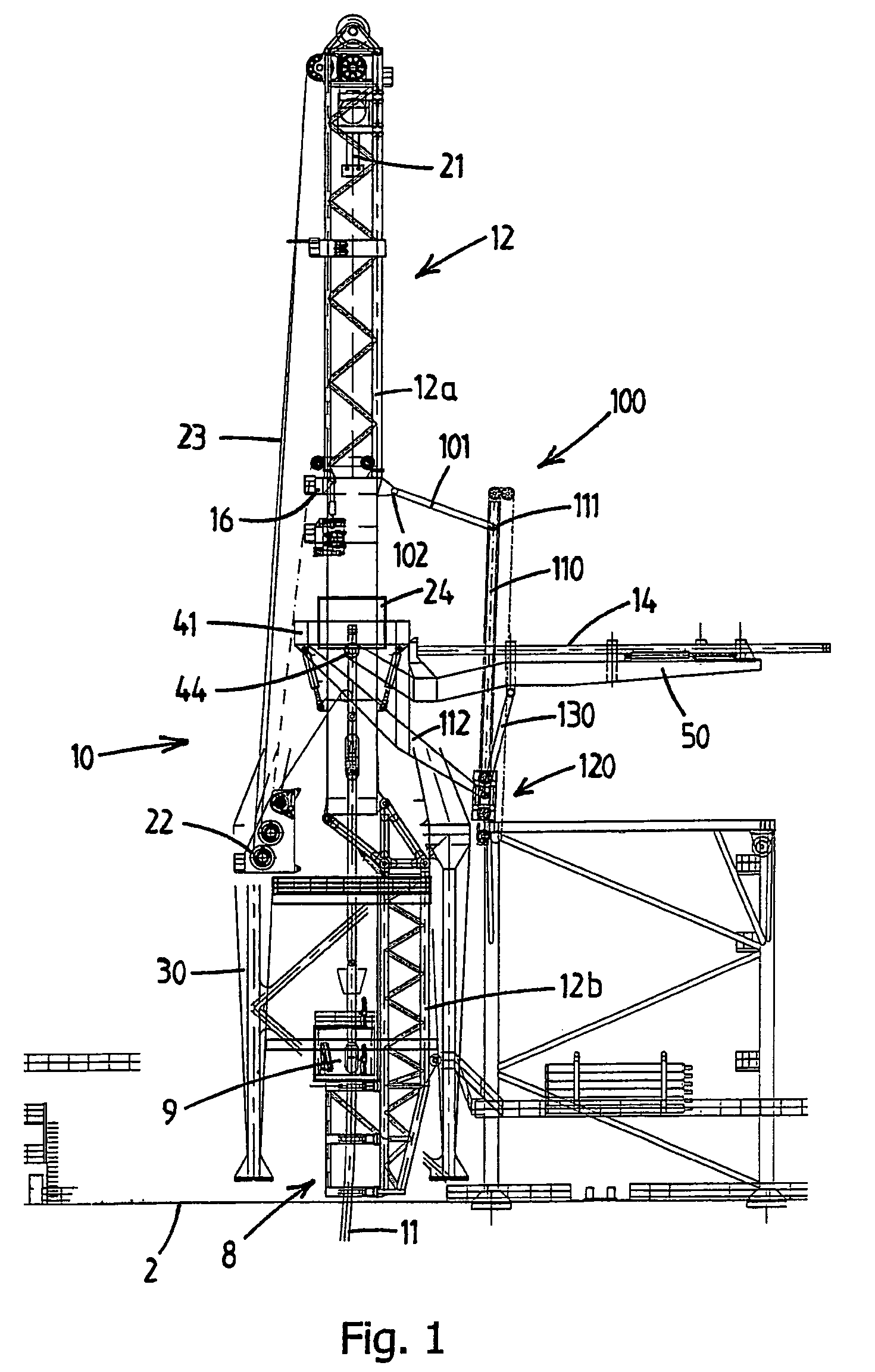
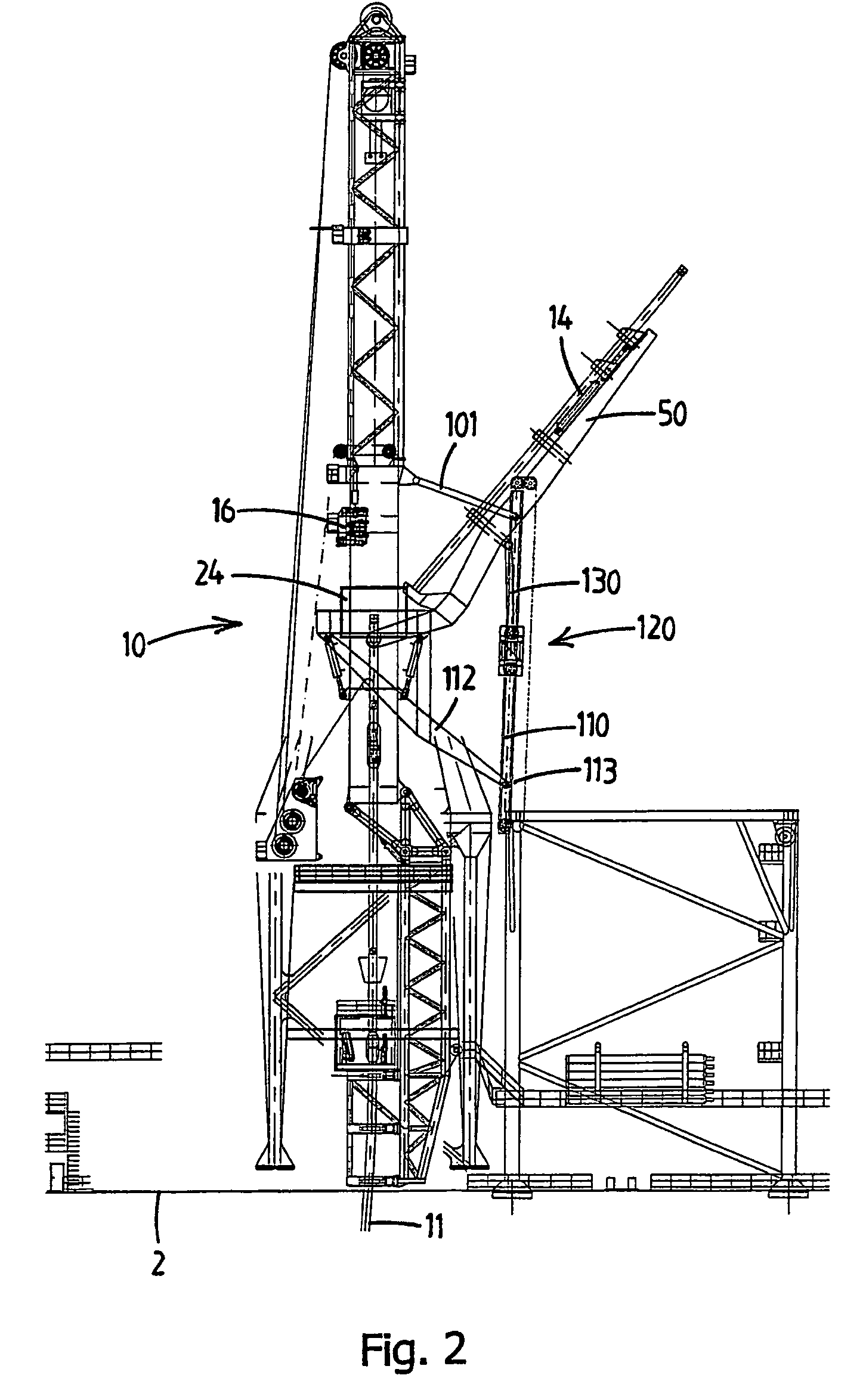
[0020]FIGS. 1-4 show an offshore vessel 1 having a deck 2 on which a marine J-lay pipelaying system 10 for laying of an offshore pipeline 11 according to the present invention is mounted. FIGS. 1-3 only show a part of the vessel 1 above the deck 2. In FIG. 4 it can be seen that the pipeline 11 is launched along a side of the vessel 1, but other locations, such as the stern or bow, or through a passage in the hull of the vessel (e.g. moonpool) are also possible. It is noted that the vessel can be of any design, such as a semi-submersible, a pontoon, etc.

[0021]The system 10 comprises a J-lay tower 12, which in the embodiment shown in this example has an upper tower structure 12a and a lower tower structure 12b. In this example lower tower structure 12b can be tilted, by means of a tilting assembly 12c at its upper end, with respect to the upper tower structure 12a, between an downwardly directed operative position and an essentially horizontal stowing position, in order not to interfe...


PUM


Abstract

A marine J-lay pipelaying system for use on a vessel for laying an offshore pipeline has a J-lay tower, a pipe connecting station, wherein said pipe section is connected to the previously launched pipeline, and J-lay tower bearing means which allow for the pivoting of the J-lay tower with respect to the vessel.The J-lay tower has a free-pivotal mode wherein the J-lay tower is freely pivotable with respect to the vessel so that the J-lay tower has an orientation independent from sea-state induced vessel motions.A pipe section loader is moveable between a loading position, wherein a new pipe section is received, and a erected position, wherein the new pipe section is aligned with the J-lay tower;The pipe section loader is provided with an automatic synchronizing system which—when the pipe section loader is moved from its loading position to its erected position—causes a synchronised pivotal motion of the pipe section loader with respect to the J-lay tower in its free-pivotal mode—at the latest as the pipe section loader reaches its erected position—, so that the new pipe section is aligned with the J-lay tower is in its free-pivotal mode.

Description

FIELD OF THE INVENTION[0001]The present invention relates to a marine J-lay pipelaying system for use on a vessel for laying an offshore pipeline. In particular the present invention relates to a pipelaying system, wherein a J-lay tower is supported on associated bearing means which allow for the pivoting of the J-lay tower with respect to the vessel.BACKGROUND TO THE INVENTION[0002]Prior art J-lay pipelaying vessels are known, wherein the J-lay tower is fixed on the vessel. In other known vessels the J-lay tower is supported on bearing means which allow to pivot the J-lay tower, so that the J-lay tower can be brought in a desired orientation and then held in said orientation. In these type of vessels, the J-lay tower, and thus the pipeline, is subjected to sea-state induced vessel motions. As the vessel often are very large, sometimes semi-submersible vessels, the sea-state induced vessel motions are in many cases not a problem.[0003]A far less generally accepted prior art design i...

Claims


Application Information

Patent Timeline
IPC IPC(8): F16L1/19E21B19/15
CPCE21B19/155F16L1/19
Inventor ROODENBURG, JOOPVAN LIERE, ERWIN VINCENT
Owner ITREC BV
Learn More