Actuator control method

a technology of actuator control and actuator, which is applied in the direction of transmission, wireless commuication services, transmission systems, etc., can solve the problems of poor reception of a signal sent, receivers can be at the range limit, and the likelihood of failure to receive certain repeated frames is high

Active Publication Date: 2010-12-14
SOMFY ACTIVITES SA
View PDF17 Cites 37 Cited by
  • Summary
  • Abstract
  • Description
  • Claims
  • Application Information

AI Technical Summary

Benefits of technology

[0011]By remedying the abovementioned drawbacks, the invention also presents the advantage of enabling the installation to be programmed more quickly, when a professional installer has a dedicated programming tool.

Problems solved by technology

However, one problem associated with radio transmission is the possibility of interference resulting in poor reception of a signal sent.
Furthermore, and without it being an interference issue, there is also the problem in such installations of a transmitter intended for overall control of a number of receivers.
Some of these remote receivers can be at the range limit, and the likelihood of failure to receive certain repeated frames becomes high.
The most significant consequences of poor reception are then particularly apparent in the case of operation of a set of products: for example, all the actuators do not start simultaneously if those connected to receivers remote from the transmitter do not correctly receive the first frame or frames.
Similarly, probably the same products risk being switched off prematurely if the last frames are not received correctly.
The result is a source of visual dissatisfaction for users, and even more so for architects, with their keen desire for facade harmony.

Method used


Image

  • Actuator control method
  • Actuator control method
  • Actuator control method

Examples


first embodiment

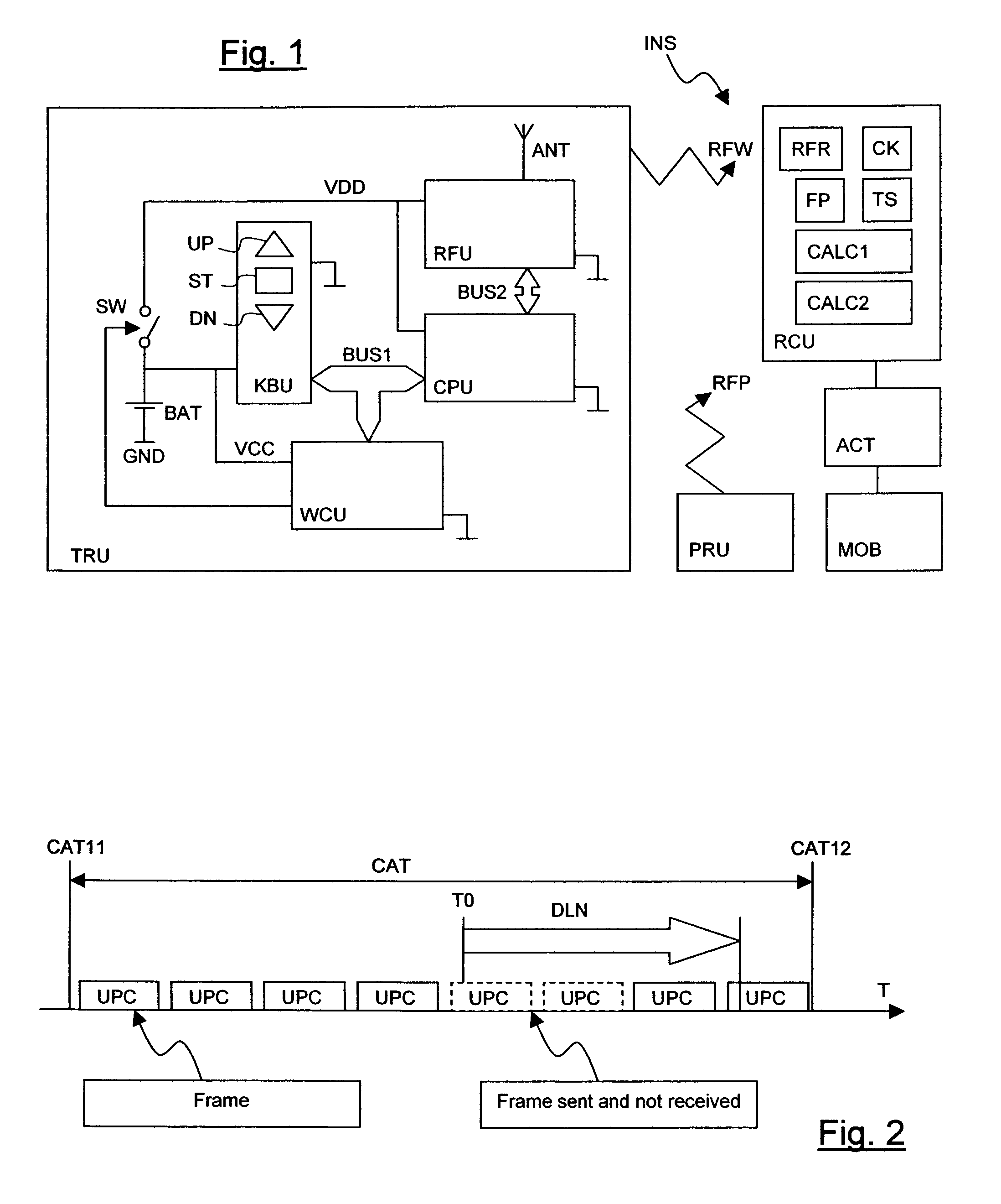
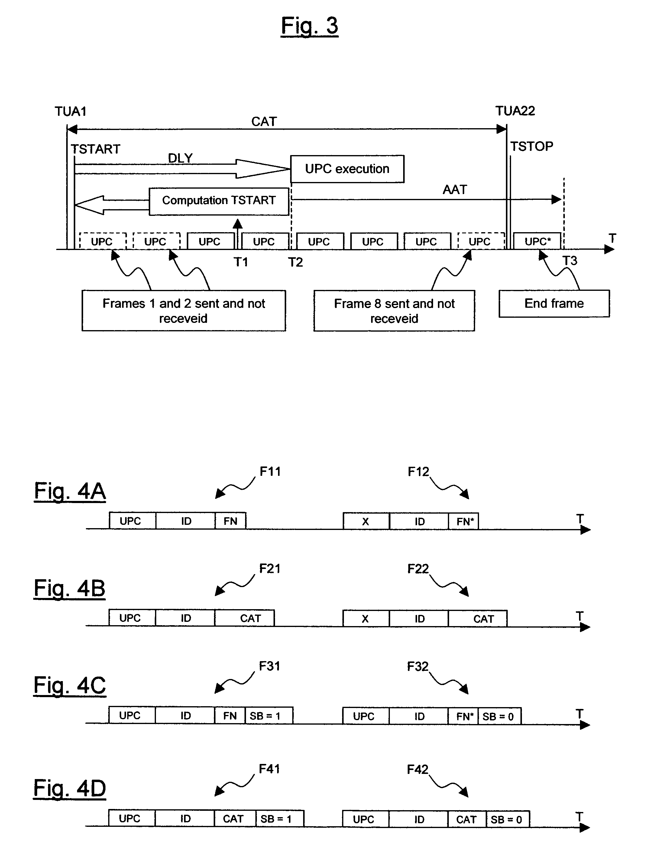
[0057] the invention is first used to enable good synchronization of all the actuators on startup. To overcome a possible transmission failure, the designer has provided for the startup of any actuator to take place at the end of the fourth frame sent (for a frame of 140 ms, this amounts to supporting a delay of around half a second). A time delay DLY is associated with this value.

[0058]At the instant T1, the receiver has therefore received its first frame. Based on the time indication contained in this frame, it computes the theoretical instant of the start of sending TSTART, close to the actual instant CAT21 of pressing on the control key. From the value of the time delay duration DLY, it computes the time remaining before activating the control UPC to be applied to the actuator. The durations can be expressed as a number of frames: for example, the duration DLY corresponds to an integer number NSTART of frame periods, in this case NSTART=4, but it is also possible to take a non-i...

second embodiment

[0085]FIG. 7 represents a synchronization method according to the invention, in which there is no desire to obtain synchronized operation of actuators obeying one and the same general command, but in which it is desired for the moving elements MOB driven by these actuators to be subject to an identical displacement, or at least a very similar displacement, after a control. The displacements are then matched by correction at end of movement.

[0086]This correction incorporates both the effects of poor reception at the start of sending and of poor reception at the end of sending.

[0087]In FIG. 7, the time information item consists of the control frame number FN and the control end frame number FN*.

[0088]In the step 701, the control received is interpreted, as in the step 601.

[0089]In the step 702, the frame number is extracted for use in the step 703 to determine the theoretical sending start instant TSTART.

[0090]Unlike the method of FIG. 6, this time the actuator is activated directly i...

third embodiment

[0100]FIG. 9 now represents a method of programming according to the invention. The method applies to the programming unit PRU, and more particularly to the programming controls that can be sent from this unit while being compatible with programming controls sent from transmission units TRU. The press on a particular PRU key provokes the sending of the control PROG. The programming method differs from the sending method of FIG. 5 solely by the content of the step 502. In FIG. 9, the corresponding step 902 is the only one shown, the steps 901 and 903-906 being like the steps 501 and 503-506 of FIG. 5.

[0101]In the step 902, the time indication introduced into the frame is deliberately offset by a quantity equivalent to the press time needed for confirmation of the control PROG by the receiver. For example, the initial press duration information item is introduced as being equal to 10 seconds, although the press has only just begun. Alternatively, the number of frames is set to the ini...


PUM


Abstract

A synchronized control method for actuators driving a moving device includes the sending of a signal repeating a frame including the code of the control to be executed, inserting into the frame sent a time information item representative of the control generation duration, extracting the time information item and computing at least one of the application start and the application end instant of control, and the reception of the signal for application of the control to the actuator as long as the generation of the control signal lasts.

Description

[0001]This application claims priority benefits from French Patent Application No. 05 02193 filed Mar 4, 2005.BACKGROUND OF THE INVENTION[0002]The invention relates to the field of wireless, radio frequency remote control of actuators driving a moving device of the building of closure (door, gate or window), solar protection, multimedia projection screen, or ventilation door type.[0003]More specifically, the invention relates to a synchronized control method for actuators driving a moving device of the building of closure (door, gate or window), solar protection, multimedia projection screen, or ventilation flap type, a control correction method, a programming method and an installation for controlling such actuators.[0004]The object of the invention is to provide a faster and more uniform reaction of the actuators, including in situations of radio environments disturbed by stray signals or by a range limit distance.[0005]The invention applies in particular to the case of remote con...

Claims


Application Information

Patent Timeline
Patent Type & Authority Patents(United States)
IPC IPC(8): H04L12/26H04M3/00H04B1/06
CPCG08C17/02
Inventor NEUMAN, SERGEFOURNET, MICHELPELLARIN, FLORENT
Owner SOMFY ACTIVITES SA
Why Eureka
Try Eureka