Instrument and associated method of trailing for modular hip stems

Active Publication Date: 2010-12-21
DEPUY PROD INC
View PDF117 Cites 49 Cited by
  • Summary
  • Abstract
  • Description
  • Claims
  • Application Information

AI Technical Summary

Benefits of technology

[0028]The technical advantage of the present inventions also include the ability of either the trial sleeve or the implant sleeve to have infinite rotation. For example, according to one aspect of the present invention, the sleeve is fitted with an internal taper over an external taper on the proximal body of the trial or implant. The connection between the proximal body trial and a sleeve is a slip fit. The connection between the proximal body implant and a sleeve is a taper lock. Thus, the present invention provides for the proximal body trial to have an absolute angular measurement of this sleeve for accurate alignment of the stem in the intramedullary canal and to the neck axis.
[0029]The technical advantage of the present invention further includes the ability to align the implant or trial either on the back table or in situ in the patient. For example, according to one aspect of the present invention, the surgical technique provides for an instrument to be used with the implant and the trial such that the proper orientation of the implant can be determined based upon the discovered and fine-tuned position of the trial found in situ on the patient or through CT scans, radiographs, or other imaging techniques. Thus, the present invention provides for a surgical technique that allows rotational alignment to be mapped from instruments to implants either on the back table or in the bone.
[0030]Another technical advantage of the present invention is that the angular position can be dialed or determined by use of a cervix coupling or teeth which may be rotated with a click type feel every, for example, ten degrees. For example, according to one aspect of the present invention, the trial includes mating gears which form a cervix coupling between the proximal body trial and the neck trial to assist in determining the relative position of the neck to the distal stem. Thus, the present invention provides simple anteversion adjustment without the need to view any marks on the prosth

Problems solved by technology

Accurate trialing of stem implants is particularly critical with difficult revision cases.
Although this can be done

Method used


Image

  • Instrument and associated method of trailing for modular hip stems
  • Instrument and associated method of trailing for modular hip stems
  • Instrument and associated method of trailing for modular hip stems

Examples


Embodiment Construction

[0074]Embodiments of the present invention and the advantages thereof are best understood by referring to the following descriptions and drawings, wherein like numerals are used for like and corresponding parts of the drawings.

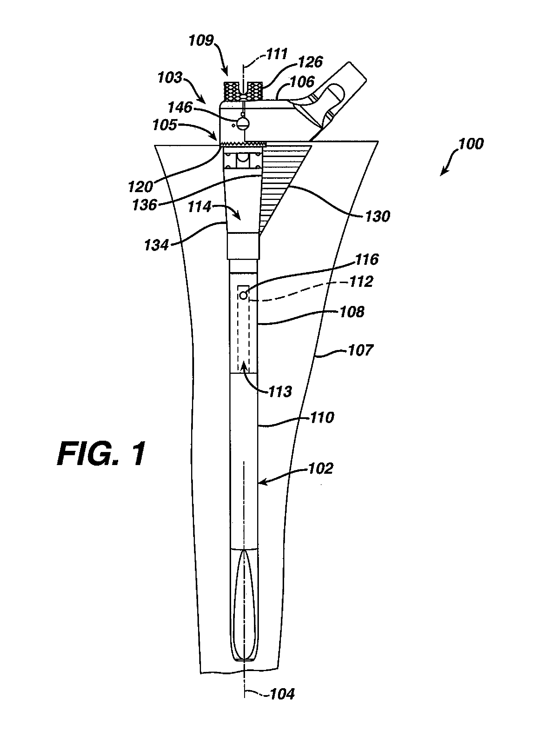
[0075]Referring now to FIG. 1, a trial 100 is shown for use in arthroplasty. Often orthopedic surgeons utilize trials such as the trial 100 to place a substitute prosthetic item in the patient's body that can be removed after the trialing or prior to the final selection of the prosthesis. Once the dimensions of the trial are verified through reduction or movements of the patient's leg through the typical motion that a patient will require, the trial is removed and is sterilized for later use in other surgeries. Conversely, a prosthetic implant, once exposed to a patient, is not utilized again. Therefore, it is important the shape, position and location of the appropriate trial be exactly duplicated by the actual implant. The trial 100 is utilized for performin...


PUM


Abstract

A trial (100) for use in performing joint arthroplasty is provided. The trial (100) fits to a cavity (103) in the canal (105) of a long bone (107) and assists in the performing of a trial reduction in performing joint arthroplasty. The trial (100) includes a stem portion (102) and a neck portion (104) fixedly connected to the stem portion (102) in a plurality of selectable positions with respect to the stem portion (102).

Description

CROSS-REFERENCE TO RELATED APPLICATIONS[0001]Cross reference is made to the following applications: U.S. patent application Ser. No. 10 / 327,187 entitled “ADJUSTABLE BIOMECHANICAL TEMPLATING & RESECTION INSTRUMENT AND ASSOCIATED METHOD”, U.S. Pat. No. 7,022,141 entitled “ALIGNMENT DEVICE FOR MODULAR IMPLANTS AND METHOD”, and U.S. Pat. No. 7,235,106 entitled “MODULAR HIP STEMS AND ASSOCIATED METHOD OF TRIALING” filed concurrently herewith which are incorporated herein by reference.TECHNICAL FIELD OF THE INVENTION[0002]The present invention relates generally to the field of orthopedics, and more particularly, to an implant for use in arthroplasty.BACKGROUND OF THE INVENTION[0003]Patients who suffer from the pain and immobility caused by osteoarthritis and rheumatoid arthritis have an option of joint replacement surgery. Joint replacement surgery is quite common and enables many individuals to function properly when it would not be otherwise possible to do so. Artificial joints are usua...

Claims


Application Information

Patent Timeline
IPC IPC(8): A61B17/56A61F2/44A61F2/32A61B17/58A61F2/00A61F2/30A61F2/36A61F2/46
CPCA61F2/36A61F2/4657A61F2/4684A61F2/367A61F2/3676A61F2002/30332A61F2002/30438A61F2002/30505A61F2002/3054A61F2002/30604A61F2002/30738A61F2002/30827A61F2002/30886A61F2002/3611A61F2002/3625A61F2002/365A61F2002/3652A61F2002/3656A61F2002/3674A61F2002/3686A61F2002/3696A61F2002/4668A61F2220/0025A61F2220/0033A61F2220/0041A61F2002/30433A61F2002/30594
Inventor DANIELS, DAVID W.DWYER, KIMBERLY A.MATTINGLY, DAVID A.
Owner DEPUY PROD INC
Why Eureka
Try Eureka