Assembly of panels of an airplane fuselage

a technology of aircraft fuselage and assembly, which is applied in the direction of railway bodies, transportation and packaging, and window arrangements, etc., can solve the problems of inconvenient assembly between said two panels, insufficient use of said ring, and virtually inevitable and rapid appearance of fatigue cracks under alternating stress, so as to reduce the protruding portion of the outer ring and improve the aerodynamics of the aircraft fuselag

Active Publication Date: 2010-12-28
AIRBUS OPERATIONS (SAS)
View PDF11 Cites 28 Cited by
  • Summary
  • Abstract
  • Description
  • Claims
  • Application Information

AI Technical Summary

Benefits of technology

[0021]Preferably, in order to further reduce the protruding portion of the outer ring and improve the aerodynamics of the aircraft fuselage, each panel comprises, substantially symmetrically on either side of the circumferential join, a face offset in depth relative to the outer face in the thickness of the panel, the outer ring being positioned wholly or partly on the two offset faces.

Problems solved by technology

On the other hand, at a circumferential join, an overlap of two panels would generate an unacceptable aerodynamic discontinuity, which justifies end-to-end assembly.
When the forces, having to be transmitted between the two panels of the fuselage by said ring, increase, in particular because of the increased dimensions and capacities of an existing aircraft, such as for example a lengthening of the fuselage, then the use of said ring to produce the assembly between said two panels is not satisfactory.
This reduction of the reserve factor results in the virtually inevitable and rapid appearance, in service, of fatigue cracks under alternating stress.
This high risk of the rapid appearance of cracks will reduce the inspection interval.
In addition, because of the complex architecture (number and stacking of parts) of the zone concerned, these cracks are very difficult to detect and the inspections will consequently be even more difficult to carry out, which may cause the first inspection to be brought forward, and then the inspection intervals to be shortened.
However, the thickening of the ring does not significantly and proportionally improve the reserve factor, the reserve factor still remaining low, in particular because of the not inconsiderable increase in the secondary bending moment in the join, a consequence of the thickening of the ring.

Method used


Image

  • Assembly of panels of an airplane fuselage
  • Assembly of panels of an airplane fuselage
  • Assembly of panels of an airplane fuselage

Examples


Embodiment Construction

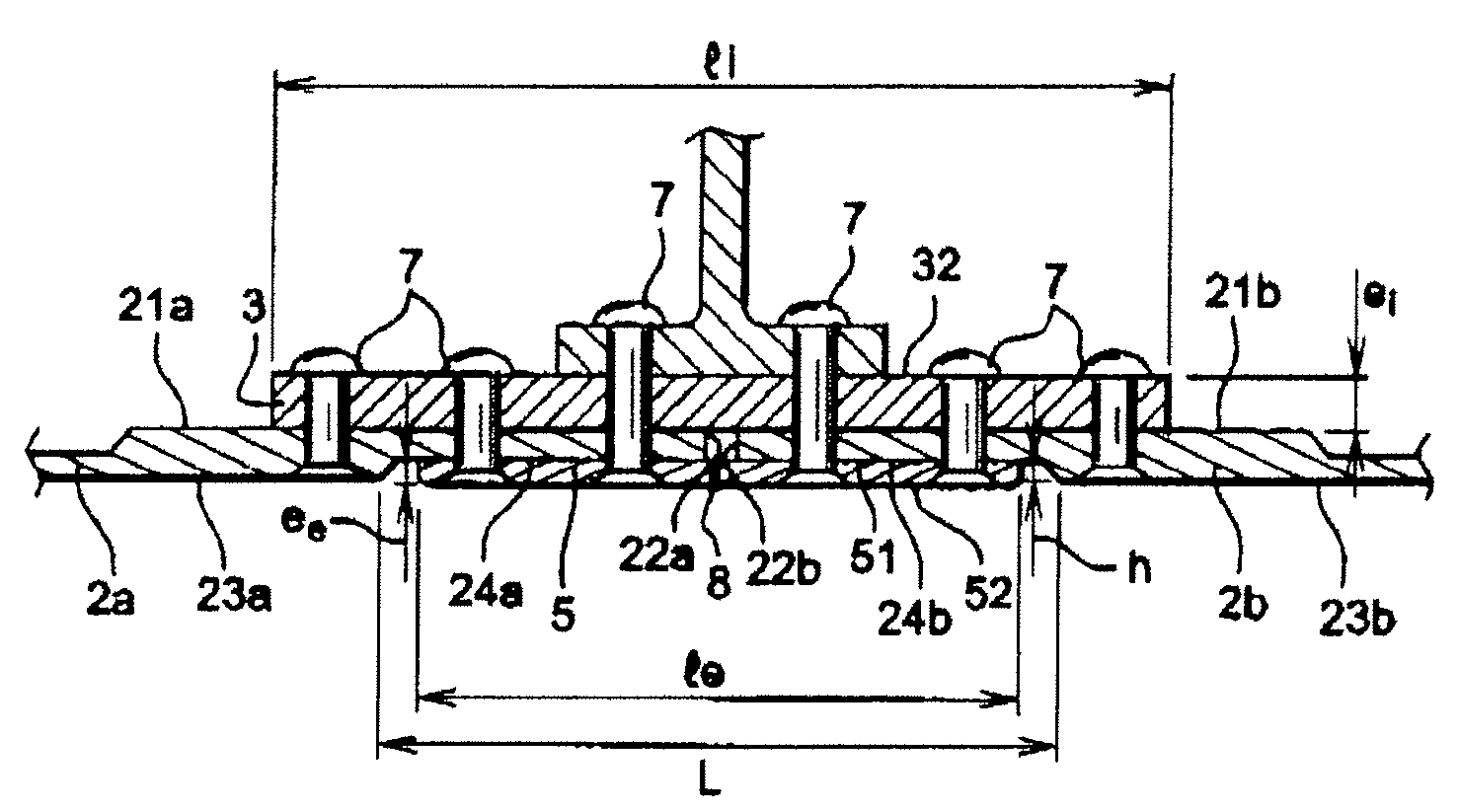
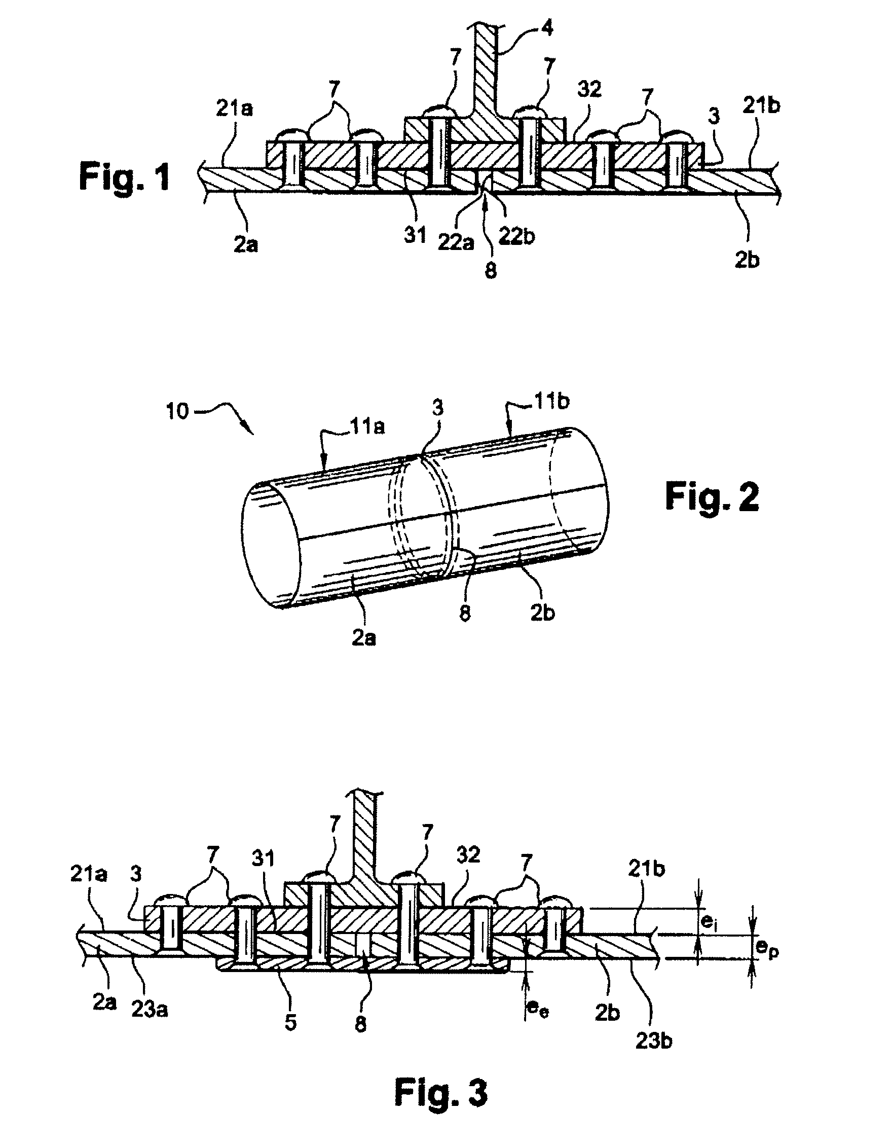
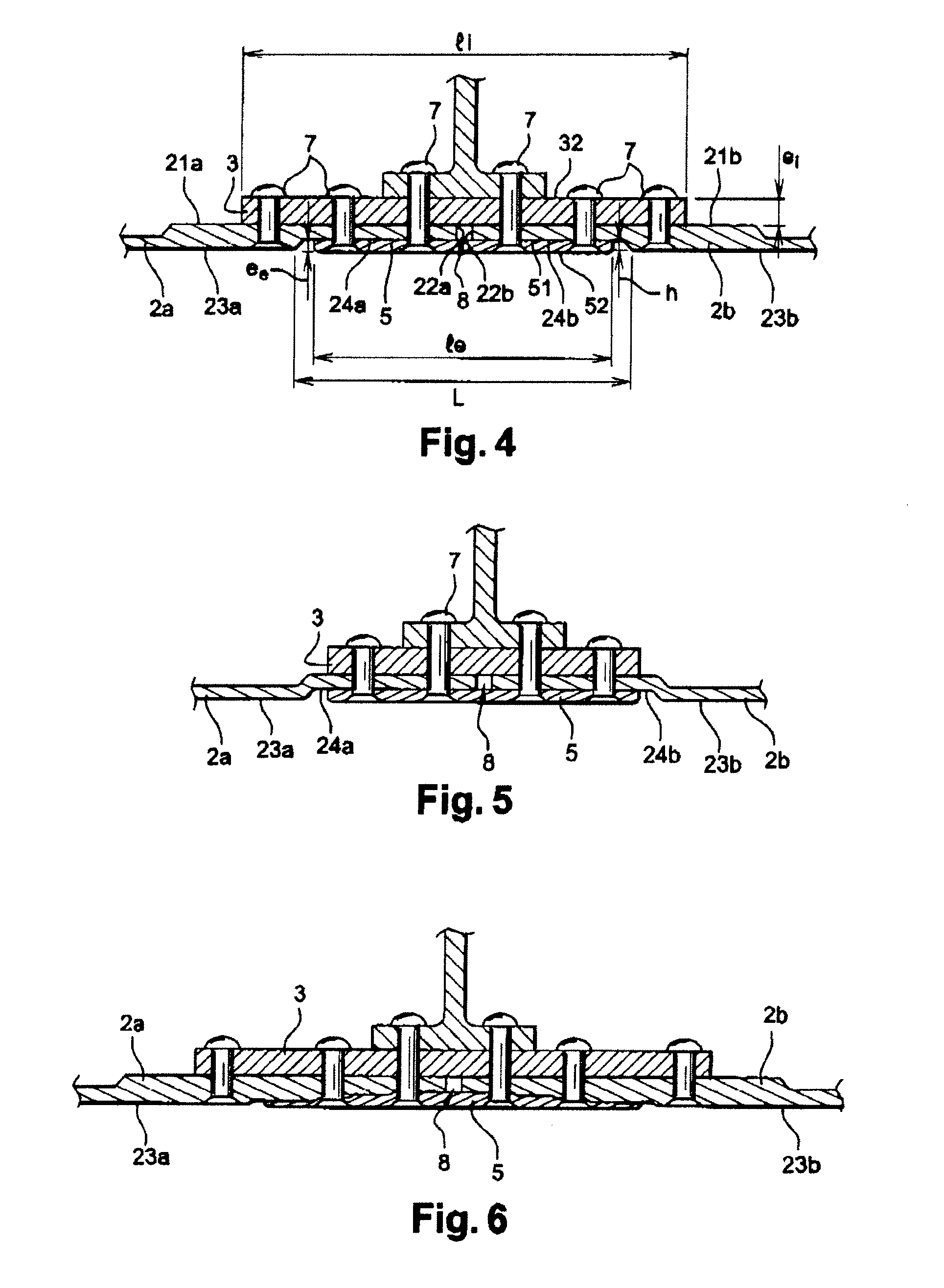
[0032]An aircraft fuselage 10, as schematized in FIG. 2, is made by the assembly of at least two sections 11a, 11b, at a circumferential join 8. Each section is made with at least one panel 2a, 2b, for example of a metallic material or of a composite material. At the circumferential join 8, the panels 2a, 2b, with a thickness ep, are assembled together by a ring 3, situated on the inside of the fuselage, called the inner ring.

[0033]The exemplary embodiment of the disclosed embodiments is described in the case of an assembly of two panels at a circumferential join, in an embodiment to suit the case of a contact zone with an aerodynamic flow, the direction of said flow being substantially perpendicular to the circumferential join in the zone in question. The disclosed embodiments may be applied to any assembly of panels apart from a circumferential join, such as for example, although of less value, at a longitudinal join, said longitudinal join corresponding to a generatrix of the fus...


PUM


Abstract

An aircraft fuselage including at least two sections kept assembled at a circumferential join, each section having at least one panel. The circumferential join includes at least one inner ring, situated on one face, called the inner face, of the fuselage. The inner ring has a width li, partially overlaps each of the two panels and is fixed to the two panels by fasteners. The fuselage also includes an outer ring, situated on one face, called the outer face, of the fuselage, opposite to the inner face. The outer ring has a width le, partially overlaps the two panels, and is fixed to the two panels and to the inner ring by some or all of the fasteners fixing the inner ring to the two panels.

Description

BACKGROUND[0001]1. Field[0002]The disclosed embodiments relate to the field of the assembly of an aircraft fuselage. More particularly, the disclosed embodiments relate to the assembly of panels of an aircraft fuselage when the forces to be transmitted between the fuselage panels are high.[0003]2. Brief Description of Related Developments[0004]An aircraft fuselage is a structure usually comprising substantially cylindrical sections butted against one another along join lines, called circumferential joins, defining planes perpendicular to the longitudinal axis of the fuselage, the sections themselves usually each consisting of several panels also assembled together along join lines, called longitudinal joins, oriented substantially along generatrixes of said fuselage.[0005]These two types of joins are zones of weakness of the fuselage that must be made to withstand the heavy stresses to which the fuselage is subjected in flight.[0006]Usually, the longitudinal joins of the fuselage ar...

Claims


Application Information

Patent Timeline
Patent Type & Authority Patents(United States)
IPC IPC(8): B64C1/00
CPCB64C1/069B64C1/12Y02T50/433B64C2001/0072Y02T50/40
Inventor NORMAND, MATHIEUCAZZOLA, MARCDEILHES, SANDRINE
Owner AIRBUS OPERATIONS (SAS)
Why Eureka
Try Eureka