
Architecture tool and methods of use

a technology of architecture and tools, applied in the field of architecture tools and methods of use, can solve the problems of not meeting the 3d requirements of metabolic and tissue engineering, requiring both expensive and timely custom fabrication, and requiring enormously invasive surgeries

Inactive Publication Date: 2010-12-28
SCIPERIO
View PDF59 Cites 191 Cited by
  • Summary
  • Abstract
  • Description
  • Claims
  • Application Information

AI Technical Summary

Benefits of technology

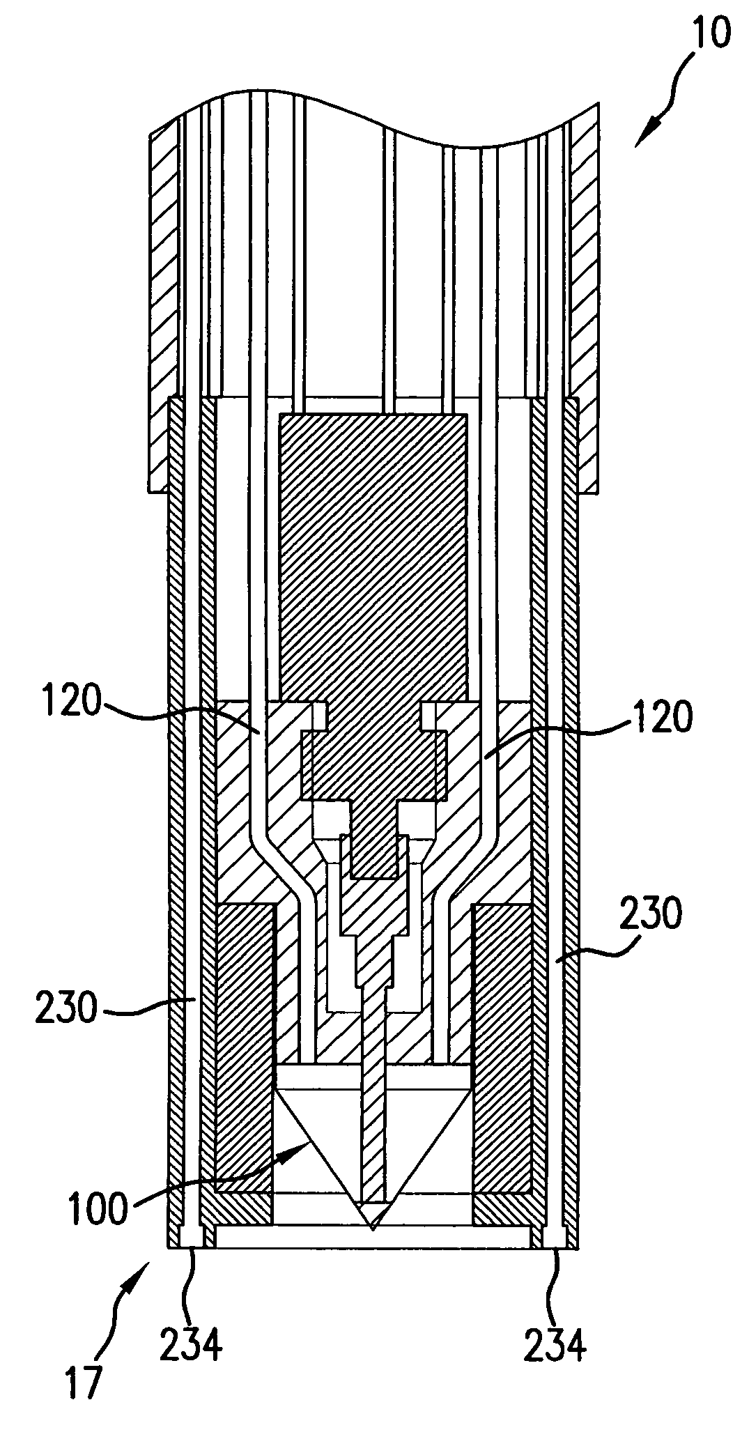
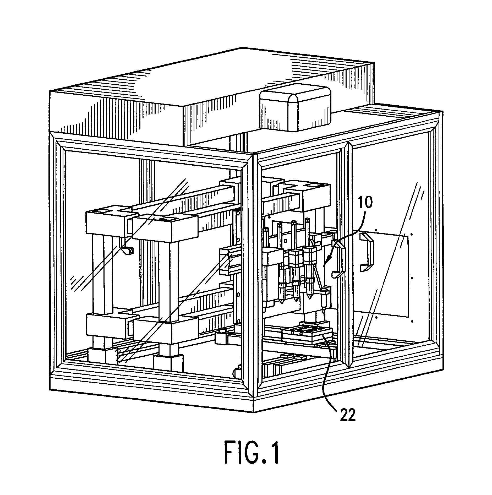
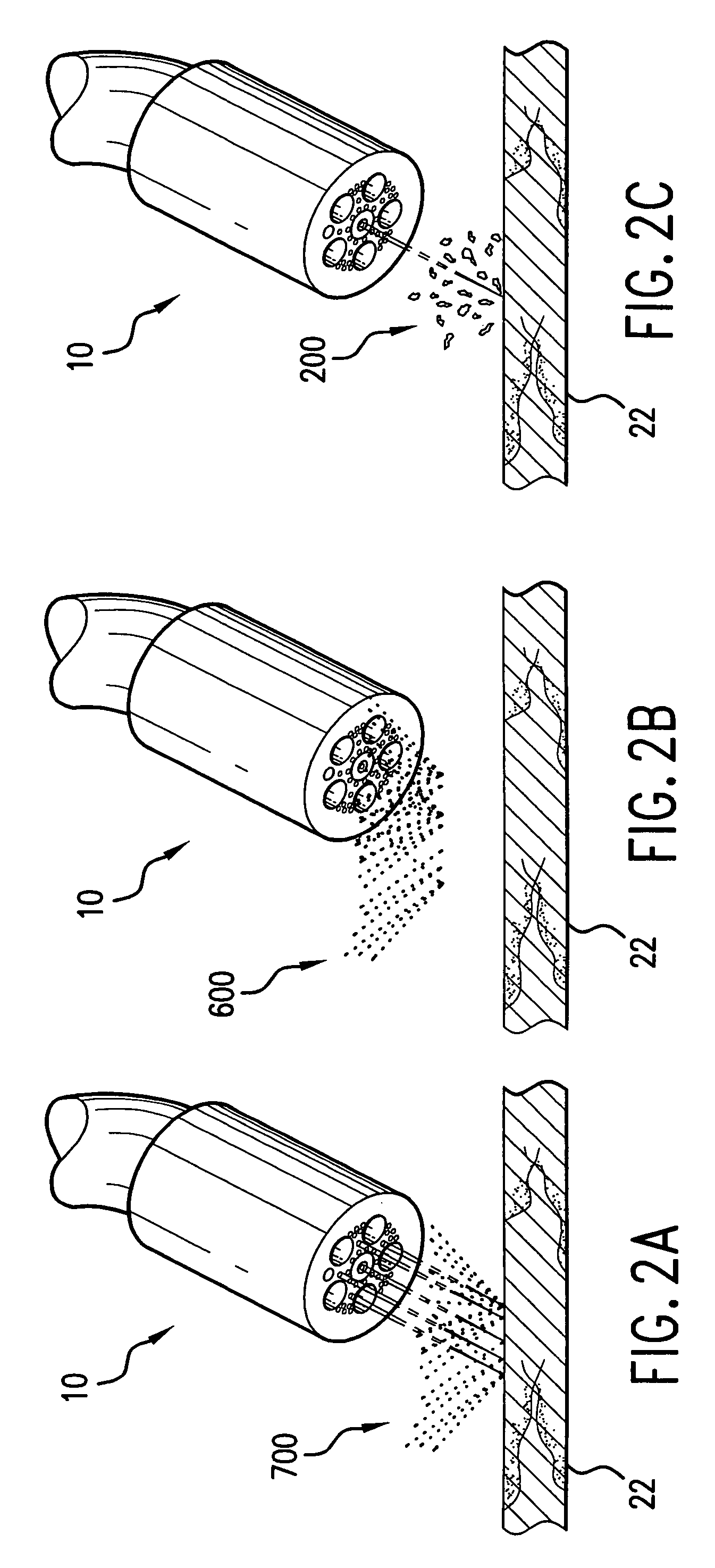
"The invention is a direct-write patterning system that can be used for both fine-pattern microdispensing and laser-beam writing over flat or conformal surfaces. The system can deposit a wide range of materials, including dielectric pastes, semiconducting pastes, conducting pastes, polymers, hydrogels, cells, growth factors, nutrients, and extracellular matrix materials. The system can be used in in vivo procedures and can also be used for non-medical applications such as fabricating electronic devices and decorative patterning. The invention provides integrated tool technologies for the direct-write deposition and laser micromachining of materials, and can be used in regenerative medicine and tissue engineering techniques. The system is small and maneuverable, allowing for in vivo procedures, and can also be used for in vitro applications."

Problems solved by technology

Current approaches, to include transplantation, transfusion of cells into a preformed implantable biocompatible matrix, or 2D in vitro culturing of tissues, require both expensive and timely custom fabrication and tremendously invasive surgeries.
Surface is italicized above to illustrate that while this technology is highly successful for such applications as cell-based assays for drug discovery and planar biosensor arrays, it does not satisfy the 3D requirements for metabolic and tissue engineering.
The option of surgical reconstruction, although usually involving the patient's own tissues, again is not appropriate for many situations and is associated with significant morbidity.
The burden to the patient and the health-care delivery system due to the extensive surgery often required and the high number of repeat procedures is no longer inline with the objectives of modern treatment preferences.

Method used


Image

  • Architecture tool and methods of use
  • Architecture tool and methods of use
  • Architecture tool and methods of use

Examples


Embodiment Construction

[0055]The present invention is more particularly described in the following examples that are intended as illustrative only since numerous modifications and variations therein may be apparent to those skilled in the art. As used in the specification and in the claims, “a,”“an,” and “the” can mean one or more, depending upon the context in which it is used. Several aspects of the present invention are now described with reference to the figures, in which like numbers indicate like parts throughout the figures.

[0056]For convenience, abbreviations and symbols used throughout this specification are set forth in the following Tables 1 and 2.

[0057]

TABLE 1ABBREVIATIONS2D, 3DN Dimensions, -DimensionalAFAutofluorescenceBCGFB-Cell Growth FactorCADComputer Aided DesignCAMComputer Aided ManufacturingCCDCharge-Coupled DeviceCFDComputational Fluid DynamicsCMUCarnegie Mellon UniversityCRTCathode Ray TubeCSFColony Stimulating FactorCTComputerized TomographyCTGFConnective Tissue Growth FactorCWConti...


PUM

PropertyMeasurementUnit
diameteraaaaaaaaaa
depthaaaaaaaaaa
center wavelengthsaaaaaaaaaa

Abstract

The invention provides an apparatus and methods for depositing materials on a substrate, and for performing other selected functions, such as material destruction and removal, temperature control, imaging, detection, therapy and positional and locational control. In various embodiments, the apparatus and methods are suitable for use in a tabletop setting, in vitro or in vivo.

Description

[0001]This application is a divisional of U.S. Ser. No. 10 / 227,146, filed Aug. 23, 2002, now U.S. Pat. No. 6,986,739, which claims priority to application Ser. No. 60 / 314,344, filed Aug. 23, 2001, which claims benefit of application Ser. No. 60 / 337,378, filed Dec. 4, 2001, which claims benefit of application Ser. No. 60 / 337,383, filed Dec. 4, 2001, which claims benefit of application Ser. No. 60 / 340,706, filed Dec. 11, 2001. The entirety of these application are incorporated herein by reference.STATEMENT OF FEDERALLY SPONSORED RESEARCH[0002]This invention was made with government support under Grant No. NBCHC010019 awarded by the Defense Advancement Research Projects Agency. The United States government may have certain rights in the invention.FIELD OF THE INVENTION[0003]This invention relates generally to tools and methods for depositing materials accurately on a selected substrate, or for performing a variety of other tasks, including material removal, imaging, and detection. The ...

Claims


Application Information

Patent Timeline
Patent Type & Authority Patents(United States)
IPC IPC(8): A61B1/12A61B5/00A61B17/00A61B18/20B05C5/02H01L21/00
CPCA61B5/0066A61B5/0073A61B5/415A61B5/418B05C5/0216B05C5/0225A61B17/00A61B18/20H01L21/6715A61M35/00C12M21/08C12M33/00B33Y30/00
Inventor WARREN, WILLIAM L.PARKHILL, ROBERT L.STEWART, ROBERT L.KACHURIN, ANATOLY M.TAYLOR, ROBERT M.CHURCH, KENNETH H.
Owner SCIPERIO
Learn More