Woodworking machine with linear direct drive

a direct drive, woodworking machine technology, applied in the direction of propulsion systems, metal sawing devices, manufacturing tools, etc., can solve the problems of relegated known per se, inability to meet the needs of production, so as to achieve greater precision, more cost-effectiveness, and robustness.

Inactive Publication Date: 2010-12-28
SIEMENS AG
View PDF34 Cites 15 Cited by
  • Summary
  • Abstract
  • Description
  • Claims
  • Application Information

AI Technical Summary

Benefits of technology

[0044]The movement of all the electrical and magnetic components to the primary part of the linear direct drive allows the latter to be designed in an encapsulated form, and allows the secondary part to be technically considerably simpler, more robust and therefore more cost-effective, than in the past.
[0045]The secondary part is advantageously in the form of a passive rail composed of magnetically permeable laminated material or solid material. A toothed stamped-out area is the secondary part, that is to say at least two different air-gap thicknesses in the movement direction, can be produced with greater precision than the previously normal magnetic secondary parts. This makes it pos

Problems solved by technology

These mechanical transmission elements are susceptible to mechanical wear, thus necessitating increased maintenance, if appropriate repair or even replacement.
Linear motors that are known per se have been relegated to the background when compared with conventional drive techniques owing to the sensitivity to faults of the external me

Method used


Image

  • Woodworking machine with linear direct drive
  • Woodworking machine with linear direct drive
  • Woodworking machine with linear direct drive

Examples


Embodiment Construction

[0076]Before explaining woodworking machines with a linear direct drive in more detail, the method of operation and possible embodiments which are relevant for a woodworking machine of a linear direct drive, also referred to in the following text as an electrical machine or as a linear motor, will be described.

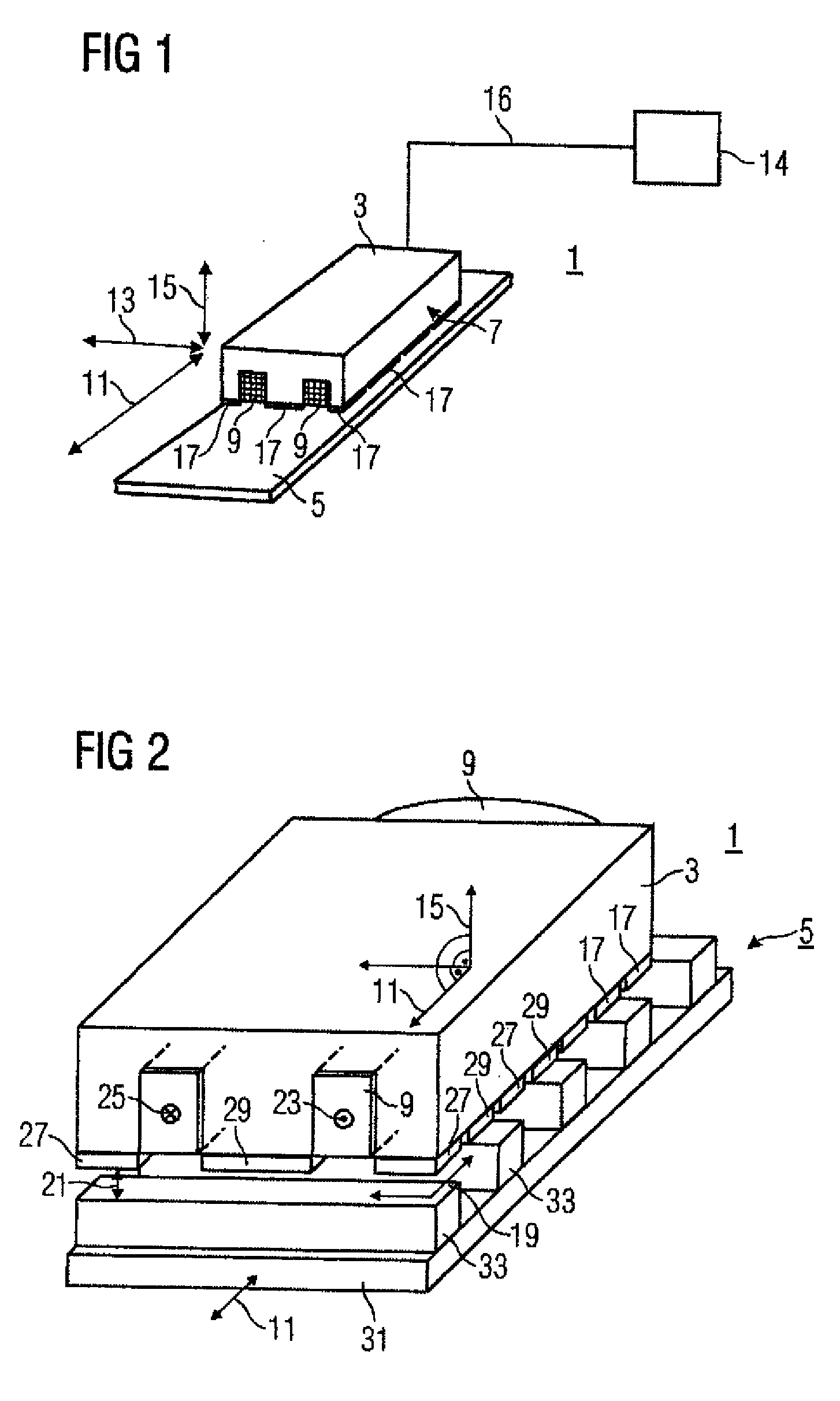
[0077]The illustration in FIG. 1 shows an electrical machine 1. The electrical machine 1 has a primary part 3 and a secondary part 5. The primary part 3 has a winding 9 and permanent magnets 17. The movement direction of the primary part 3 is indicated by means of a double-headed arrow running in the longitudinal direction 11. A further double-headed arrow indicates the lateral direction 13. A third double-headed arrow indicates the normal 15, with the normal relating to an air-gap plane 19, although the air-gap plane 19 is not illustrated in FIG. 1. The air-gap plane 19 is, however, illustrated in FIG. 2. An arrow indicates a side view 7 which relates to the illustration in F...


PUM

PropertyMeasurementUnit
Magnetic fieldaaaaaaaaaa
Widthaaaaaaaaaa

Abstract

The aim of the invention is to provide a robust, simple woodworking machine. To achieve this, the invention provides a machine comprising at least one linear direct drive, which contains a primary part (3, 3a, 3b, 4, 4a, 4b) with a first element (9, 10, 12, 14) for generating a first magnetic field and at least one additional element (17, 18, 20, 27, 28, 29, 30) for generating an additional magnetic field. The first element (9) for generating the first magnetic field is positioned, in particular, in such a way in relation to the additional element (17, 18, 20, 27, 28, 29, 30) for generating the additional magnetic field that the first magnetic field overlaps the additional magnetic field. The machine also comprises a secondary part (5, 6, 6a, 6b), which comprises magnetic return elements and is devoid of magnetic sources. According to the invention, the primary part (3, 3a, 3b, 4, 4a, 4b) and/or the secondary part (5, 6, 6a, 6b) is or are suitable for guiding or placing at least one workpiece and/or for guiding and/or placing at least one tool for machining the workpiece.

Description

BACKGROUND OF THE INVENTION[0001]The invention relates to a woodworking machine having at least one linear direct drive, which has a primary part and a secondary part.[0002]Woodworking machines have numerous linear movements. For example, the workpieces must be transported and machined, and the tools must be set, and auxiliary material must be supplied, with these processes having been carried out until now by means of conventional drive technology and mechanical transmission elements such as gearboxes, rack pinions and ball-roller spindles. These mechanical transmission elements are susceptible to mechanical wear, thus necessitating increased maintenance, if appropriate repair or even replacement.[0003]The achievable accuracies and the desired processor speeds are likewise considerably reduced by the dirt resulting from machining residues such as chips or shavings or dust and corrosive process environments, such as lubricant residues, glue or sealants.[0004]Linear motors that are k...

Claims


Application Information

Patent Timeline
IPC IPC(8): H02K41/02
CPCB23D47/04B23D47/042B23D47/08H02K41/033H02K1/223H02K2213/03
Inventor ARMEIT, HANS ULRICHBURGSTAHLER, RALPHJAJTIC, ZELJKOKNORR, MARKUSRUST, ANDREASSCHIELE, STEFANSCHIRDEWAHN, HARTMUTSCHULTHEISS, ROLAND
Owner SIEMENS AG
Why Eureka
Try Eureka