Power supply providing ultrafast modulation of output voltage

a power supply and output voltage technology, applied in the direction of high-frequency amplifiers, amplifiers with semiconductor devices/discharge tubes, gain control, etc., can solve the problems of oversizing the expensive rf components, reducing the efficiency of power amplifiers, and significant portion of supply energy

Active Publication Date: 2010-12-28
ASTEC INT LTD
View PDF59 Cites 101 Cited by
  • Summary
  • Abstract
  • Description
  • Claims
  • Application Information

AI Technical Summary

Problems solved by technology

At every instance when the envelope of the rf signal is substantially lower than the maximum allowed by the supply voltage, the efficiency of the power amplifiers is severely reduced.
In other words, a significant portion of the supply energy is expensed only for maintaining the power amplifier's operating point (bias) without creating useful signal.
There are a number of adverse effects caused by this phenomenon, including (i) the need to oversize the expensive rf components in the amplifier system, (ii) increased cooling requirements, (iii) increased size and weight of equipment, and (iv) increased consumption of electrical energy.
However, while rf powe

Method used


Image

  • Power supply providing ultrafast modulation of output voltage
  • Power supply providing ultrafast modulation of output voltage
  • Power supply providing ultrafast modulation of output voltage

Examples


Embodiment Construction

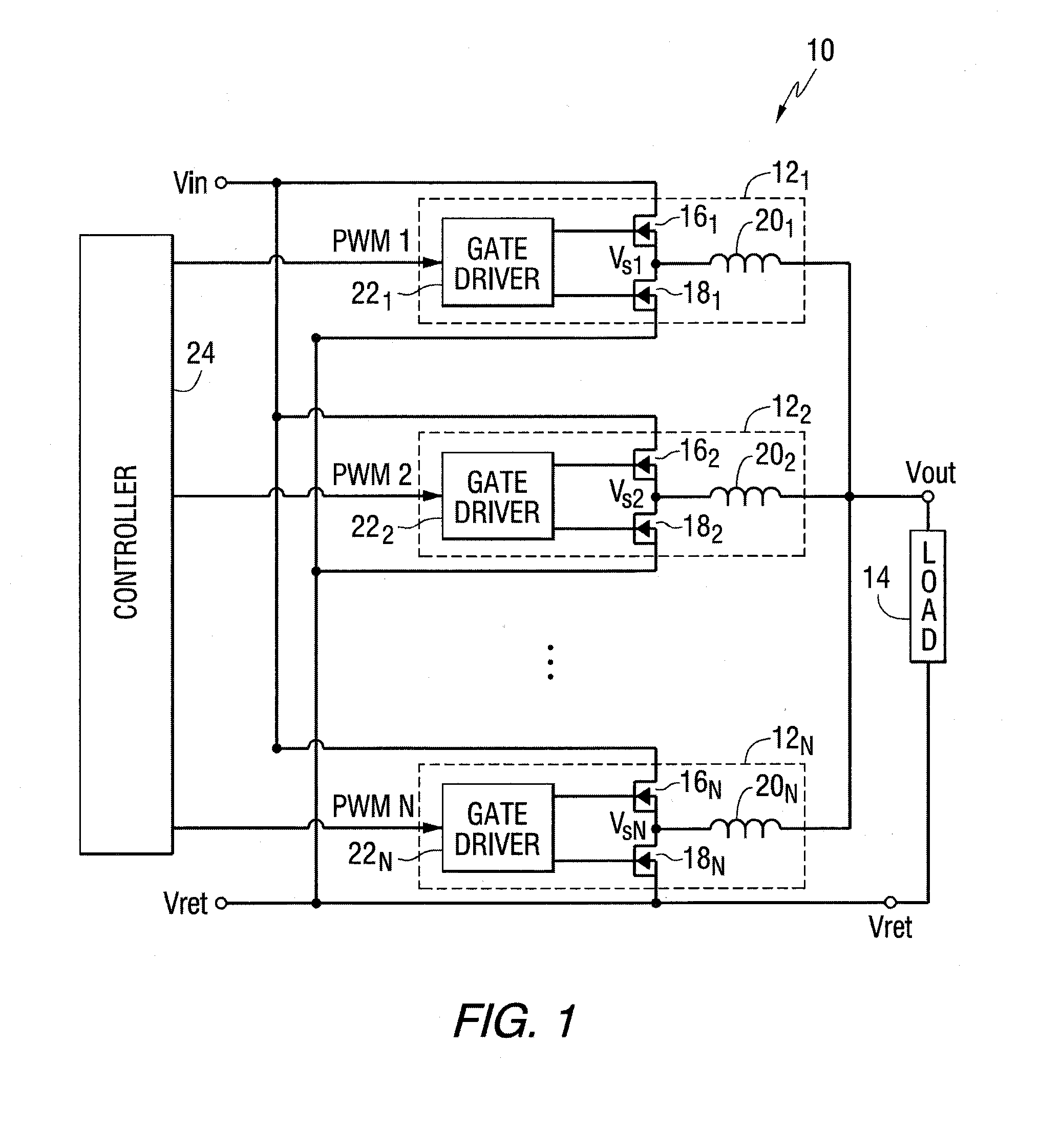
[0023]FIG. 1 is a diagram of a power supply 10 according to various embodiments of the present invention. The power supply 10 includes a member (N) of parallel-connected, switch-mode power modules 121−N. The power modules 121−N may each convert a common input voltage (Vin) to respective output voltages of the same average amplitude, which allow the modules 121−N to be connected together (Vout) as shown in FIG. 1 to power a load 14.

[0024]Each of the power modules 121−N may be identical in structure but operated, as explained in more detail below, in a phase-shifted (or “interleaved”) manner relative to each other. As shown in FIG. 1, according to one embodiment, each power module 121−N may include, for example, a synchronous buck converter. In that connection, the power modules 121−N may include, among other things, a power switch 161−N, a synchronous rectifier 181−N, an output inductor 201−N and a gate driver 221−N for providing the gate signals to the power switches 161−N and the s...


PUM


Abstract

A circuit for use with a power amplifier that amplifies an input signal. The circuit may comprise an amplitude correction circuit and an open-loop switching regulator. The amplitude correction circuit may be configured to generate a corrected envelope signal from an input envelope signal that represents an envelope of the input signal. The open-loop switching regulator may be connected to the amplitude correction circuit and may be for powering the power amplifier based on the corrected envelope signal. According to various embodiments, the corrected envelope signal generated by the amplitude correction circuit is a function of the input envelope signal and an error voltage of the open-loop switching regulator.

Description

PRIORITY CLAIM[0001]This application claims the benefit of U.S. Provisional Application Ser. No. 60 / 894,570, filed on Mar. 13, 2007, which is incorporated herein by reference.BACKGROUND[0002]The present invention generally concerns power conversion circuits.[0003]A number of different electronic devices require very fast modulation of their supply voltage. One such type of electronic devices is radio frequency (rf) linear power amplifiers. Such amplifiers are widely used in modern wireless communication devices and infrastructure. In complex modulation schemes commonly used in wireless communications like QPSK, CDMA, WCDMA, the amplitude of the envelope of the rf signal varies significantly. At every instance when the envelope of the rf signal is substantially lower than the maximum allowed by the supply voltage, the efficiency of the power amplifiers is severely reduced. In other words, a significant portion of the supply energy is expensed only for maintaining the power amplifier'...

Claims


Application Information

Patent Timeline
IPC IPC(8): H03G3/20H03F3/04
CPCH03F1/0227H03F1/3247H03F3/19H03F3/217H02M2001/0045H03F2200/102H03F2200/432H03F2201/3233H02M1/0045
Inventor MARKOWSKI, PIOTRWANG, LIN GUO
Owner ASTEC INT LTD
Why Eureka
Try Eureka