Noise reduction in optical communications networks

a technology of optical communication network and noise reduction, applied in the field of noise reduction in optical communication network, can solve the problems of broadband noise which passes into the system degrading the osnr (optical signal to noise ratio) of the added signal, and affecting the osnr of the add path signal

Active Publication Date: 2010-12-28
TELEFON AB LM ERICSSON (PUBL)
View PDF28 Cites 7 Cited by
  • Summary
  • Abstract
  • Description
  • Claims
  • Application Information

AI Technical Summary

Benefits of technology

[0018]This has the further advantage of further improving the OSNR of the add path signal.

Problems solved by technology

Use of add couplers has the disadvantage of incurring losses and causing the add power level to require amplification.
This in turn causes broadband noise which passes into the system degrading the OSNR (optical signal to noise ratio) of the added signals as well as those signals passing through the photonic add / drop node.
The signal to noise ratio is therefore worst when the loss of the add path is less than the maximum loss possible.

Method used


Image

  • Noise reduction in optical communications networks
  • Noise reduction in optical communications networks
  • Noise reduction in optical communications networks

Examples


Embodiment Construction

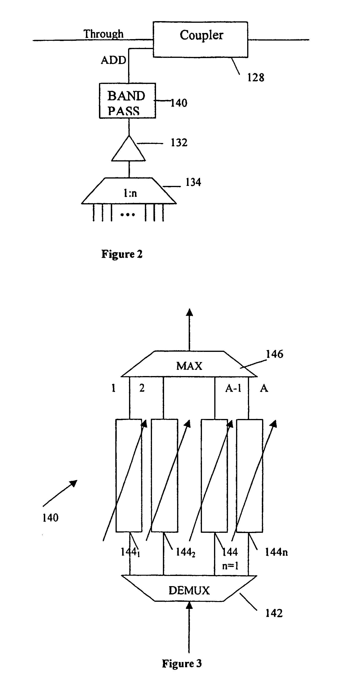
[0024]The add path shown in FIG. 2 comprises a 32:1 combiner 134 which combines the 32 signal channels to produce a single output signal which is amplified by amplifier 132 and then passed to a WDM multiplexer / demultiplexer device 140. This device is illustrated in more detail in FIG. 3. The output of the device 140 forms the add input to add coupler 128 on one of the E / W and W / E paths of the network.

[0025]FIG. 3 shows the mux / demux device 140 in more detail. The device comprises an optical demultiplexer 142 which receives the multiple wavelength input signal and splits it into n single wavelength outputs. In this example, n=32 and is the number of channels supported by the network. Each of the 1 to n outputs of the demultiplexer 142 is passed through an individual variable optical attenuator (VOA) 144(1) . . . 144(n). The outputs of the 32 variable optical attenuators form the 1 to 32 inputs to an optical multiplexer 146 which remultiplexes the 32 signal paths to output a DWDM mult...


PUM


Abstract

The add path of a dense wavelength division multiplexing (DWDM) add/drop node comprises an n:1 coupler for combining n signal sources. The combined signal is amplified and then demultiplexed. Each output of the demultiplexer is passed through a variable optical attenuator (VOA) and the VOA outputs multiplexed to form the add signal. Channels carrying no add signal and not used to control the added signals are attenuated to zero to remove a broadband noise contribution from those channels. The signal sources are run at maximum power and the signals of those channels are attenuated by the respective VOAs to control their amplitude and optimize the optical signal to noise ratio of the add signal.

Description

BACKGROUND OF THE INVENTION[0001]This invention relates to the reduction of noise in optical communications networks, and in particular, to the reduction of noise in an add path where signals are placed onto the network at a network node.[0002]Add / Drop multiplexers are widely used in optical communications networks to provide wavelength non-specific add / drop ports. This allows random transponder provisioning and tuneability. FIG. 1 shows an example of how add / drop multiplexers are used. The optical network is a dual fibre DWDM optical network with one fibre 10 carrying traffic in an East / West direction and the other fibre 12 in a West / East direction. The terms East and West are conveniently used to describe the direction in which network traffic travels and does not correspond to geographical East or West. The traffic is a multiplex, typically, of 32 wavelength channels. At network nodes, traffic is taken off the network and split into the component channels using an optical demulti...

Claims


Application Information

Patent Timeline
Patent Type & Authority Patents(United States)
IPC IPC(8): H04J14/02H04Q3/52H04B10/00H04B10/25H04B10/2507H04B10/2581H04B10/27H04B10/29H04B10/291H04J14/00
CPCH04J14/0204H04B2210/258H04J14/0205H04J14/0221
Inventor CLARINGBURN, HARRY RICHARDSHARRATT, MICHAEL
Owner TELEFON AB LM ERICSSON (PUBL)
Why Eureka
Try Eureka