Prosthesis, in particular prosthetic foot

Inactive Publication Date: 2011-01-04
BAUERFEIND GMBH & CO
View PDF36 Cites 53 Cited by
  • Summary
  • Abstract
  • Description
  • Claims
  • Application Information

AI Technical Summary

Benefits of technology

[0016]Through the invented prosthesis, in particular the invented implementation of the universal joint mechanism, an extremely compact modeling of the human foot can be achieved which can be oriented such that the two rotational axes can be disposed in positions which, with respect to one another, are oriented in positions corresponding to the human ankle joint. With the invented foot prosthesis, consequently, a dyn

Problems solved by technology

In the course thereof extremely complex processes are taking place in the region of the lower extremities.
It must be taken into consideration that leg amputees are often patients with at least a restricted degree of mobility, whose training status is weakly developed so that additional efforts caused by the dynamic behavior of the prosthetic device could further restrict the degree of mobility.
A nonsymmetric gait pattern due to a prosthesis can moreover lead to unusually strong stress or even to wear phenomena on the healthy leg as well as on the still functioning knee joint ligament of the amputated leg.
In addition to the disablement due to the amputation, hip damage, dama

Method used


Image

  • Prosthesis, in particular prosthetic foot
  • Prosthesis, in particular prosthetic foot
  • Prosthesis, in particular prosthetic foot

Examples


Embodiment Construction

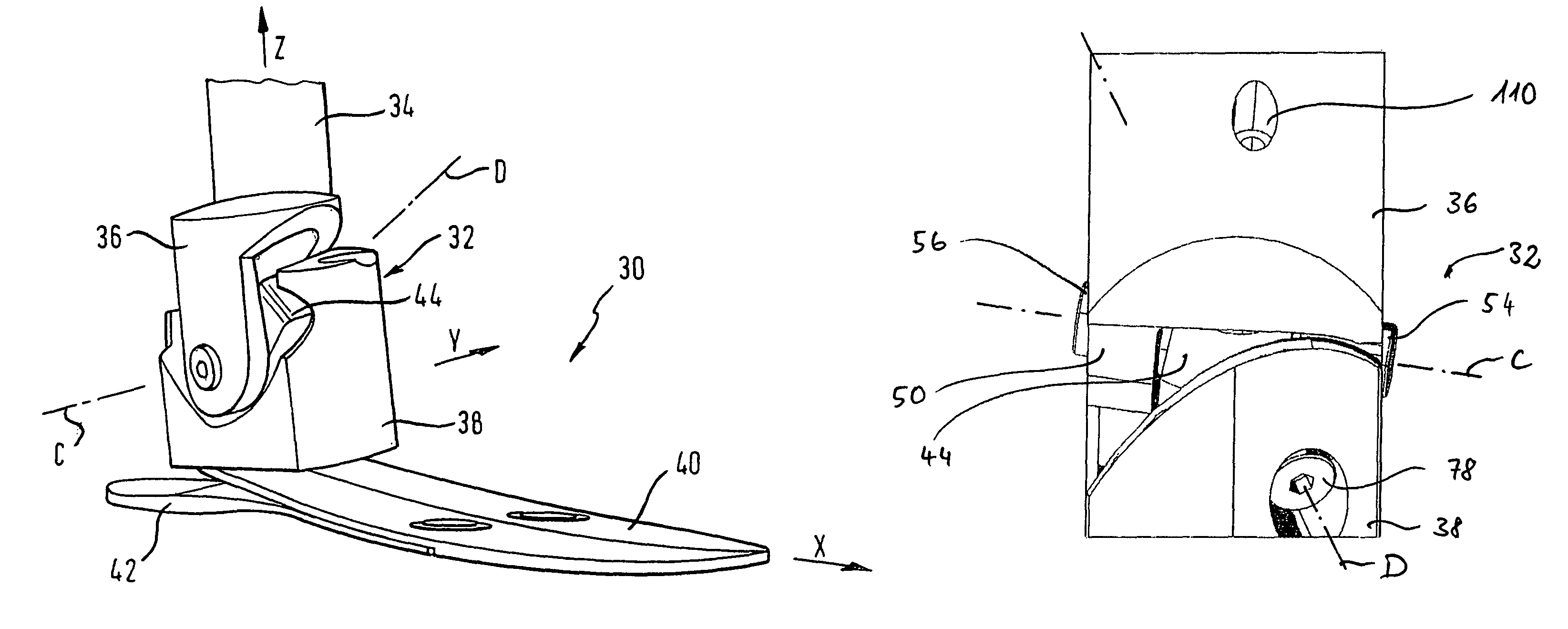
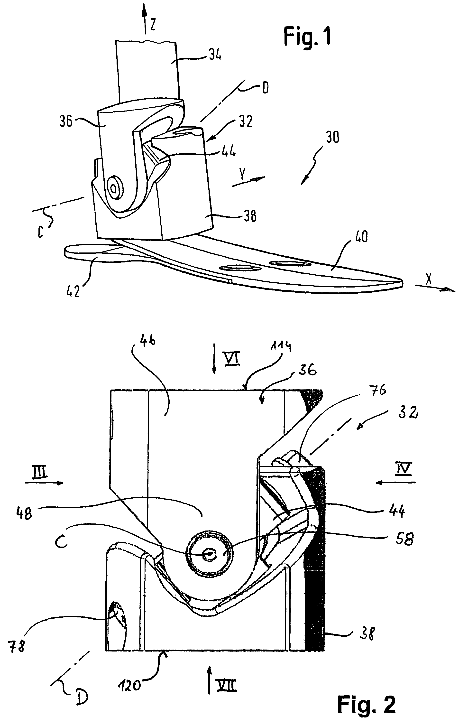
[0058]An invented prosthesis device is in FIG. 1 overall denoted by 30.

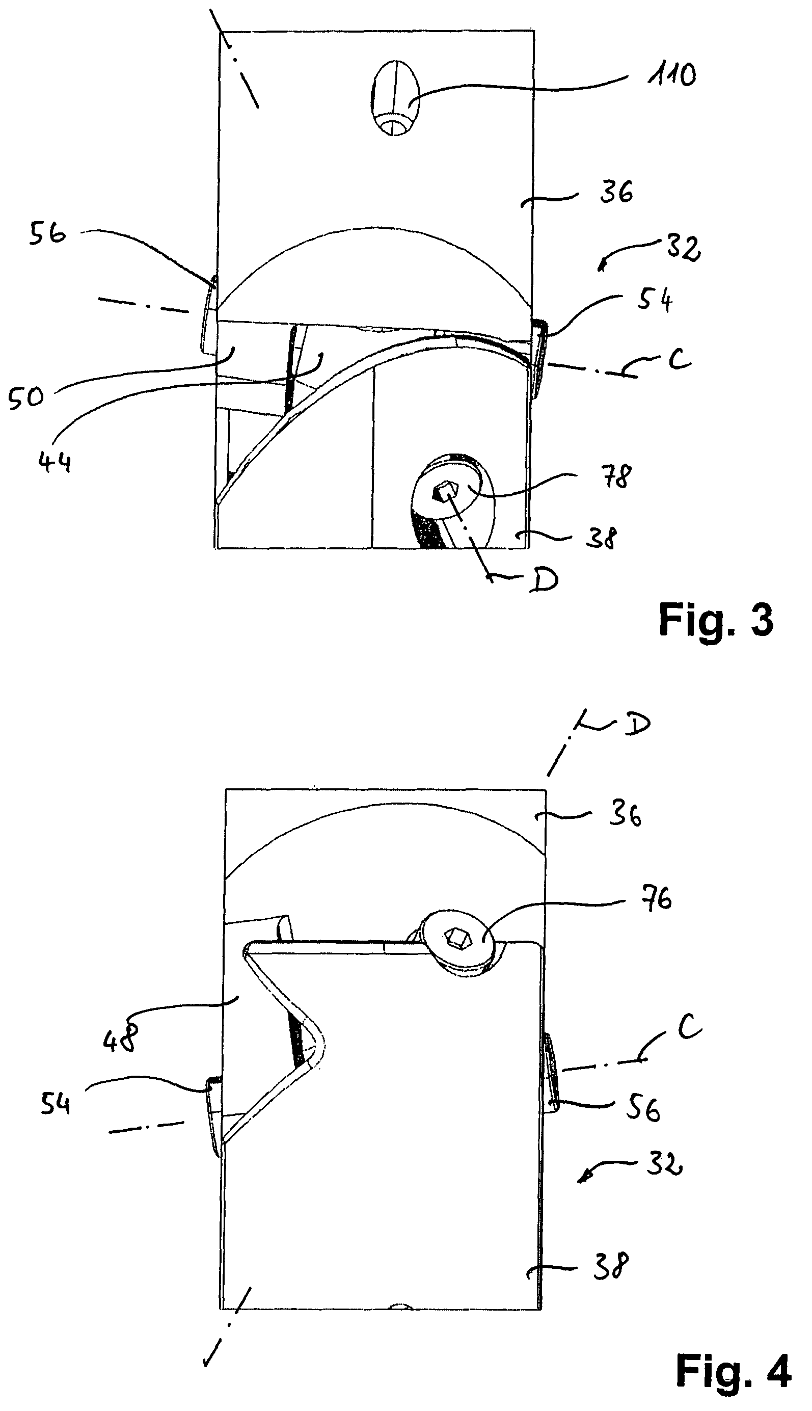
[0059]It comprises a universal joint mechanism 32 coupled with a shaft 34, shown schematically, to a shaft-side joint fork 36. The universal joint mechanism 32 comprises further a treading-side joint fork 38, to which a treading attachment 40 with a heel element 42 is secured. The treading attachment 40 and the heel element 42 are resilient, for example in the form of carbon fiber layers connected with one another.

[0060]These two joint parts implemented as joint forks 36 and 38 are rotatably connected with one another via a joint element 44. In particular the shaft-side joint fork 36 is rotatable about a first rotational axis C relative to a joint element 44. The treading-side joint fork 38 is rotatable about a second rotational axis D relative to the joint element 44. Rotational axes C and D of FIG. 1 are only schematically drawn and do not exactly reproduce the progression of these rotational axes proper. This ...


PUM


Abstract

The invention relates to a prosthetic device (30), in particular a foot prosthesis, for fitting leg amputees, with a universal joint mechanism (32), which couples a shaft (34) with a treading attachment (40, 42) through an articulation, wherein the universal joint mechanism (32) comprises a joint element (44) supported such that it is rotatable about a first rotational axis (C) and a second rotational axis (D) differing therefrom. For more accurate modeling of the natural gait of a healthy human foot, the invention provides that the universal joint mechanism (32) comprises a shaft-side joint fork (36) coupleable with the shaft (34) and a treading-side joint fork (38) coupled via the joint element (44) through an articulation with the shaft-side joint fork (36), wherein the shaft-side joint fork (36) is swivellable about the first rotational axis (C) and the treading-side joint fork (38) about the second rotational axis (D) relative to the joint element (44), and wherein the swivel movements of shaft-side and treading-side joint fork (36, 38) relative to the joint element (44) are carried out against the resistance of at least one damping element (90, 92) proximal to the joint element.

Description

[0001]This is a §371 of PCT / EP2005 / 008420 filed Aug. 3, 2005, which claims priority from German Patent Application No. 10 2004 037 877.0 filed Aug. 4, 2004.BACKGROUND OF THE INVENTION[0002]The present invention relates to a prosthesis, in particular a foot prosthesis, for the fitting of leg amputees, according to the preamble of patent claim 1.[0003]The biomechanical processes of human walking are composed of a plurality of movements of individual body parts. In the course thereof extremely complex processes are taking place in the region of the lower extremities. Here various joints cooperate synchronously and synergistically in order to cushion the reaction forces occurring at the point of origin, which means the treading plantar-Surface of the foot, in order to conduct propelling forces efficiently into the ground and to compensate potential unevennesses on the ground such that the rest of the body does not need to perform energy consuming compensatory movements. The joints in th...

Claims


Application Information

Patent Timeline
IPC IPC(8): A61F2/66A61F2/68
CPCA61F2/6607A61F2002/30434A61F2002/5003A61F2002/5009A61F2002/5018A61F2002/503A61F2002/5072A61F2002/6642A61F2002/6685A61F2220/0041A61F2310/00011A61F2002/30433
Inventor KLOOS, RALFGRAB, ARMINGRUNWALD, JULIASCHNEIDER, URSVON LUBTOW, KAI
Owner BAUERFEIND GMBH & CO
Why Eureka
Try Eureka