Electric field applying magnetic recording method and magnetic recording system

a magnetic recording and magnetic recording technology, applied in special recording techniques, instruments, metal sheet core heads, etc., can solve the problems of difficult voltage application in non-wiring ultra-high density recording media such as hard disk drives, unstable control, and difficult formation of such layers

Inactive Publication Date: 2011-01-04
HITACHI LTD
View PDF22 Cites 4 Cited by
  • Summary
  • Abstract
  • Description
  • Claims
  • Application Information

AI Technical Summary

Problems solved by technology

The method disclosed in the JP-A No. 2006-65927, however, inverts not only the magnetic field, but also the voltage, so that the method makes controlling unstable due to the variation of the work function on the inverted surface and changes of the probe floating height.
Forming such layers is very difficult.
In addition, as a recording medium as described above, such a wiring type memory as MRAM, which is lower in density than hard disk drives, is expected and it is difficult to apply a voltage in a non-wiring ultra-high density recording medium such as hard disk drives.
Nevertheless, variation of the distance between the medium surface and the metal probe comes to unavoidably cause variation in both positive and negative sizes, as well as in the polarity of the electric field applied necessarily to invert the object magnetizing direction.

Method used


Image

  • Electric field applying magnetic recording method and magnetic recording system
  • Electric field applying magnetic recording method and magnetic recording system
  • Electric field applying magnetic recording method and magnetic recording system

Examples


first embodiment

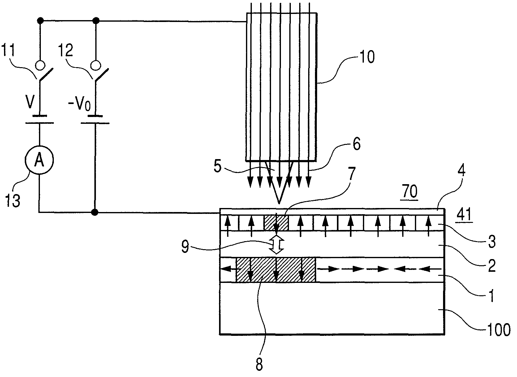
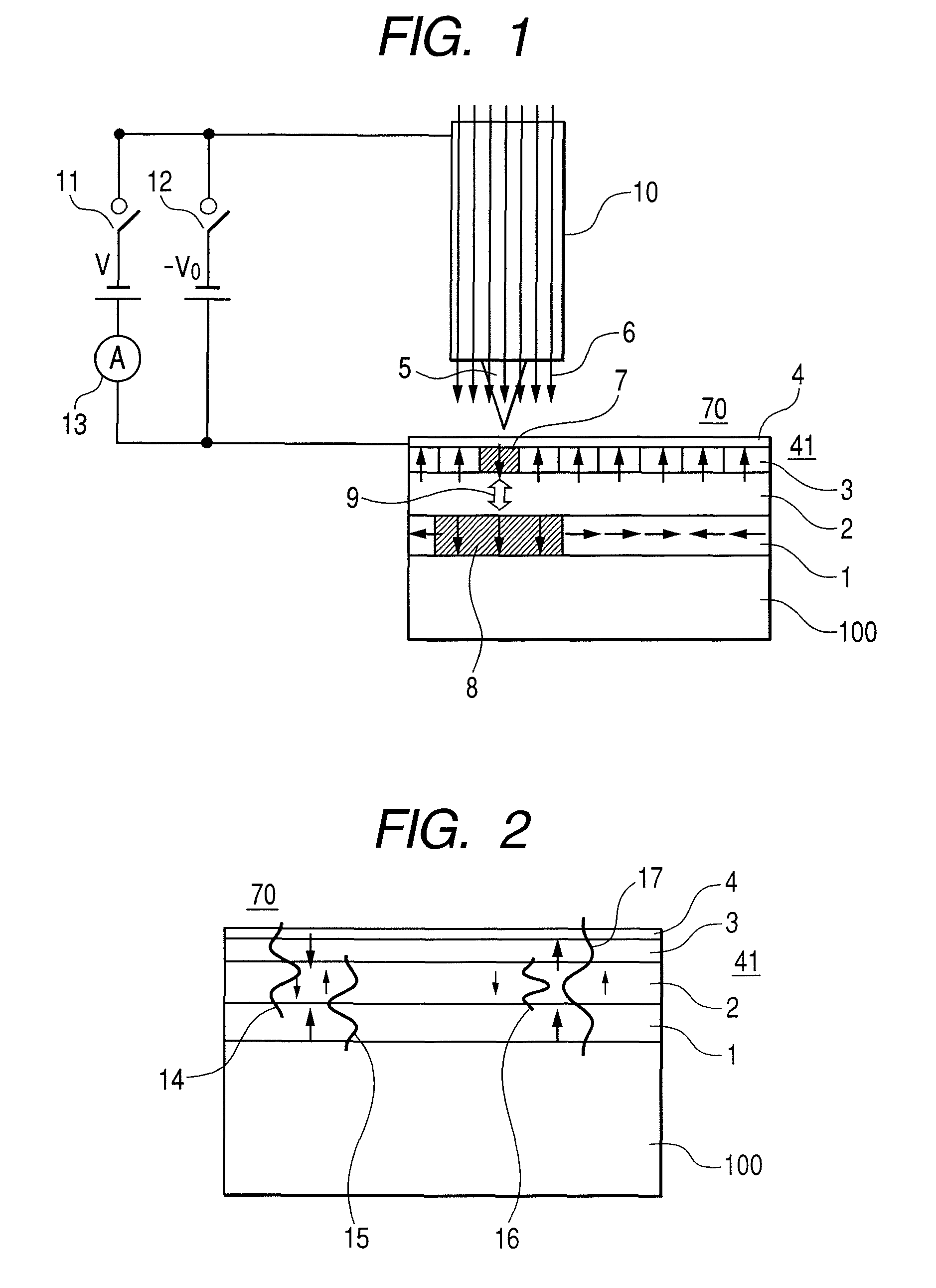
[0048]Hereunder, a first embodiment of the present invention will be described with reference to FIGS. 1 through 3. FIG. 1 shows a first embodiment of the present invention, which is a concept diagram for showing configurations of a magnetic recording medium 70, as well as a metal probe 5 and a magnetic pole 10 provided so as to face the medium 70. The magnetic recording medium 70 consists of a substrate 100 and a multilayer film 41 formed on the substrate by stacking a first ferromagnetic layer (low coercivity) 1, a nonmagnetic layer 2, a second ferromagnetic layer (high coercivity) 3, and a protection layer 4 sequentially.

[0049]It is assumed here that the highly coercive ferromagnetic layer 3 and the lowly coercive ferromagnetic layer 1 have coercivity values of Hc2 and Hc1, respectively. It is also assumed here that those ferromagnetic layers have a relationship of Hc12 with the externally applying magnetic field H.

[0050]A metal probe 5 is disposed so as to face the surface of th...

second embodiment

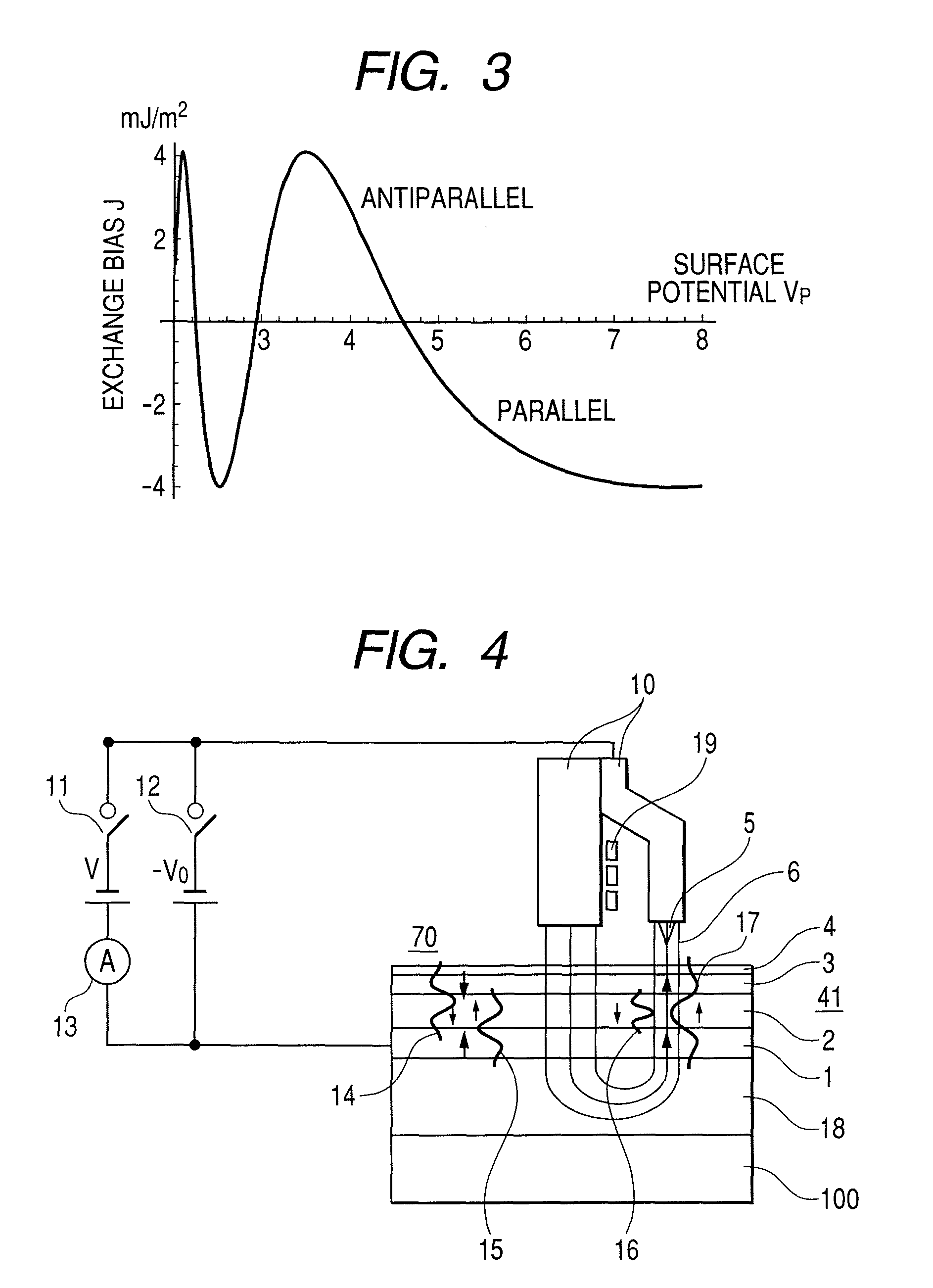
[0090]As shown in FIG. 4, a soft magnetic layer 18, a lowly coercive ferromagnetic layer 1, a nonmagnetic layer 2, a highly coercive ferromagnetic layer 3, and a protection film 4 are stacked sequentially on a substrate 100 to be formed as a multilayer film 41. It is arranged here that a voltage −V0 can be applied between the metal probe 5 and the multilayer film 41.

[0091]Here, the protection film 4 is made of, for example, such a nonmagnetic noble metal as Au. Although the magnetizing direction of the lowly coercive ferromagnetic layer 1 is in parallel to the film surface while no magnetic field is applied in the first embodiment, the magnetizing direction is perpendicular to the film surface in this second embodiment. For example, if the lowly coercive ferromagnetic layer 1 is formed as a continuous film made of FePt, CoPt, CoPd, CoCrPt, FePd, etc., the layer becomes a lowly coercive ferromagnetic layer that is magnetized perpendicularly to the film surface.

[0092]Just like the fir...

third embodiment

[0095]As shown in FIG. 6, a magnetic recording medium 70 consists of an antimagnetic layer 25, a ferromagnetic layer 26, a nonmagnetic layer 27, a lowly coercive ferromagnetic layer 1, a nonmagnetic layer 2, a highly coercive ferromagnetic layer 3, and a protection film 4 that are stacked sequentially on a substrate 100 to be formed as a multilayer film 41. It is arranged here so that a voltage −V0 can be applied between the metal probe 5 and the multilayer film 41.

[0096]Here, the protection film 4 is made of a nonmagnetic matter such as Au. The antimagnetic layer 25 works to fix the magnetizing direction of the ferromagnetic layer 26 in one direction. An exchange interaction works between the ferromagnetic layer 26 and the lowly coercive ferromagnetic layer 1, so that the lowly coercive ferromagnetic layer 1 is magnetized fixedly in one direction in parallel or in antiparallel to the magnetizing direction of the lowly coercive ferromagnetic layer 26. Then, the metal probe 5 is brou...


PUM

PropertyMeasurementUnit
diameteraaaaaaaaaa
magnetic exchange interaction energyaaaaaaaaaa
work functionaaaaaaaaaa

Abstract

A method for writing information on a highly coercive recording medium stably with an electric field applied through a metal probe and with a magnetic field applied from external and an information recording system that employs the method. The recording medium includes a substrate, a first ferromagnetic layer formed on the substrate, a nonmagnetic layer formed on the first ferromagnetic layer, and a second ferromagnetic layer formed on the nonmagnetic layer. The coercivity Hc2 of the second ferromagnetic layer is larger than that Hc1 of the first ferromagnetic layer. A magnetic field H is applied to the magnetic recording medium from a magnetic pole to change the magnetizing direction of the first ferromagnetic layer to a direction of the applied magnetic field, then a positive or negative voltage V is applied between the metal probe and the magnetic recording medium to change the quantum well level energy between the first and second ferromagnetic layers, thereby inducing an exchange magnetic field HE. As a result, the magnetizing direction of the second ferromagnetic layer is changed with both the exchange magnetic field HE and the magnetic field H.

Description

CLAIM OF PRIORITY[0001]The present application claims priority from Japanese application JP 2006-253719 filed on Sep. 20, 2006, the content of which is hereby incorporated by reference into this application.FIELD OF THE INVENTION[0002]The present invention relates to a method for writing and reading magnetization information and a magnetic recording system that employs the method.BACKGROUND OF THE INVENTION[0003]A conventional hard disk drive (HDD) employs a method that uses a magnetic head for writing magnetization information with a magnetic field generated from a coil.[0004]Now, hard disk drives are demanded further to cope with higher density recording and their magnetic head tip parts are required to be fabricated more finely to meet the refinement of the recording domain being progressed in accordance with the requirements of such higher density recording. However, it is estimated that the magnetic field intensity to be generated from a magnetic head is lowered along with the ...

Claims


Application Information

Patent Timeline
Patent Type & Authority Patents(United States)
IPC IPC(8): G11B5/147
CPCG11B5/66G11B9/1418G11B11/002G11B5/82B82Y10/00G11B2005/001G11B11/26
Inventor OGAWA, SUSUMUTAKAHASHI, HIROMASA
Owner HITACHI LTD
Why Eureka
Try Eureka