Modular data transmission system with separate energy supply for each connected module

a data transmission system and module technology, applied in the field of module data transmission system, can solve the problems of no longer being able to put into a defined state and energy supply of modules, and achieve the effect of reliable energy supply for all modules

Active Publication Date: 2011-01-04
PHOENIX CONTACT GMBH & CO KG
View PDF10 Cites 8 Cited by
  • Summary
  • Abstract
  • Description
  • Claims
  • Application Information

AI Technical Summary

Benefits of technology

[0006]The invention is based on the objective of developing a modular data transmission system that makes it possible to realize a reliable supply of energy to all modules and to ensure essentially error-free data transmission between the modules.

Problems solved by technology

If a module fails or is removed, the modules that follow this module can no longer be supplied with energy and therefore can no longer be put into a defined state.

Method used


Image

  • Modular data transmission system with separate energy supply for each connected module
  • Modular data transmission system with separate energy supply for each connected module
  • Modular data transmission system with separate energy supply for each connected module

Examples


Embodiment Construction

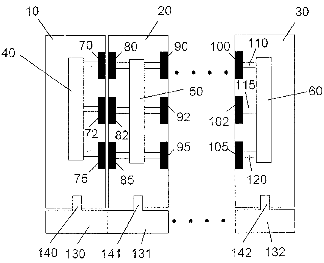
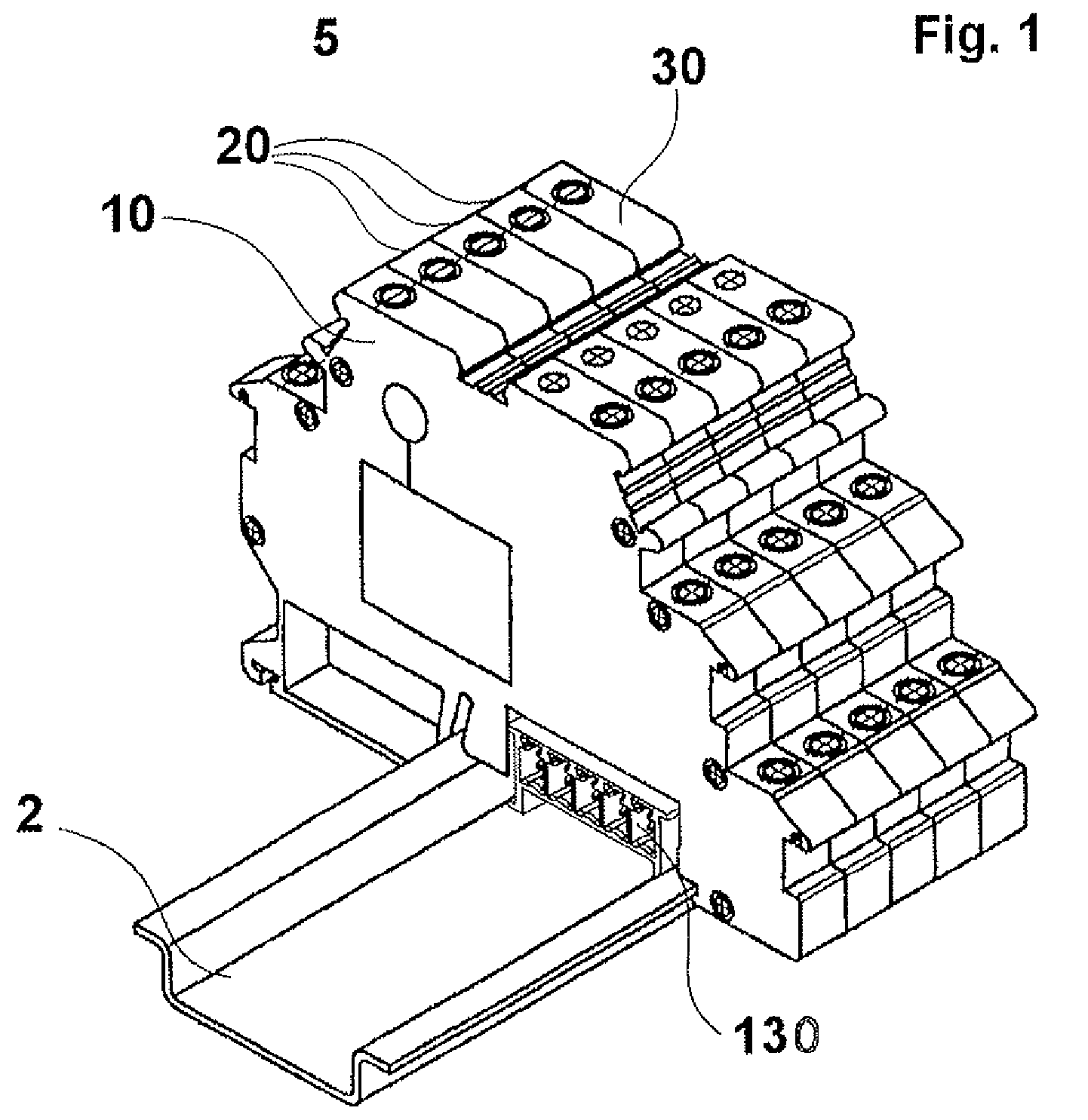
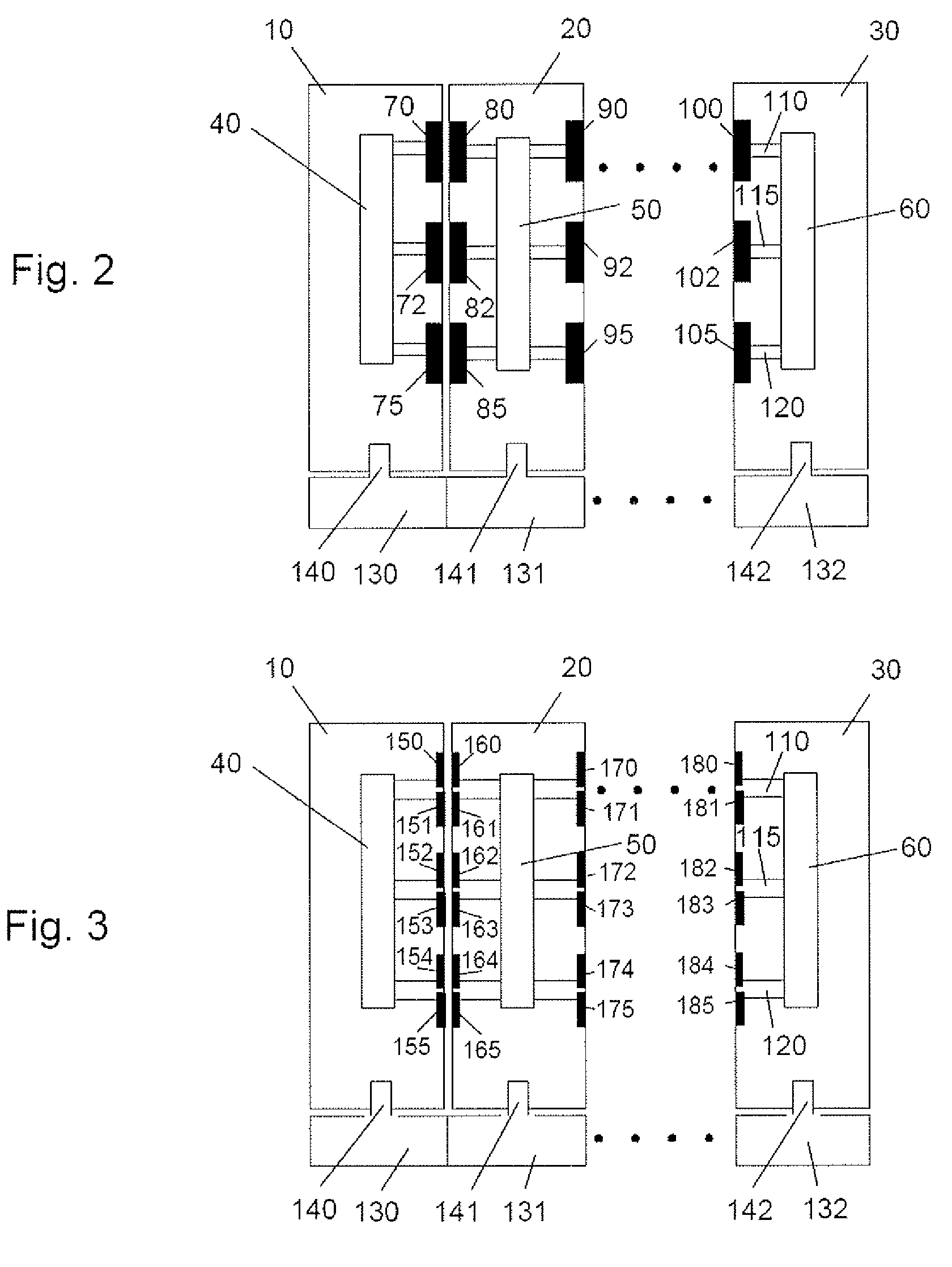
[0029]FIG. 1 shows an exemplary modular data transmission system 5 in the form of a local bus system that may be installed in a (not-shown) switchgear cabinet. The modular data transmission system 5 features a mounting rail 2 on which several bus receptacles are arranged. Only the bus receptacle 130 is partially visible in the figure. Several bus nodes are arranged on the mounting rail 2 laterally adjacent to one another in a row by being snapped onto the mounting rail 2. In this example, five bus nodes are snapped onto the mounting rail. Each bus node is mechanically and electromagnetically coupled to a bus receptacle in the snapped-on state. The bus receptacles serve for positioning the given bus nodes and supplying them with energy, as described in greater detail below. Other embodiments, in which energy is not supplied to each bus node via the bus receptacles, are also described in greater detail below. In the present example, the first outer bus node 10 on the left forms a boun...


PUM


Abstract

The invention pertains to a modular data transmission system with several modules or bus nodes that can be arranged adjacent to one another in a row. The data transmission system comprises a first bus node that features a first transmitter for the wireless transmission of data and an electrical connector, as well as a second bus node that features a first receiver for the wireless reception of data and an electrical connector. Both bus nodes are detachably fixed on a mounting rail such that they are arranged adjacent to one another in a row. The first and second bus nodes are respectively detachably connected to a bus receptacle, wherein each bus receptacle features an electrical mating connector that is coupled to the electrical connector of the respective bus node in the connected state in order to transmit energy, as well as a positioning device for positioning the respective bus node.

Description

FIELD OF THE INVENTION[0001]The invention pertains to a modular data transmission system with several modules or bus nodes that can be arranged adjacent to one another in a row.BACKGROUND OF THE INVENTION[0002]A bus system of this type is known, for example, from DE 296 24 219 U1. The bus system contains several bus nodes that are arranged adjacent to one another in a row and snapped onto a mounting rail. The bus nodes feature coupling devices that make it possible to realize contactless data transmission between the bus nodes. Each bus node features electrical contacts for connection to a power supply unit.[0003]In a modularly designed control system known from DE 196 40 367 A1, the energy supply of the modules and the transmission of information between the individual modules is realized electromagnetically. If a module fails or is removed, the modules that follow this module can no longer be supplied with energy and therefore can no longer be put into a defined state.[0004]Anothe...

Claims


Application Information

Patent Timeline
Patent Type & Authority Patents(United States)
IPC IPC(8): G06F13/00
CPCH01R9/2675H01R13/6633H04B5/02H04B5/0037H04B5/0031
Inventor KUSCHKE, DETLEVDERKSEN, JOHANNHOFFMANN, MICHAELGREWE, STEPHANWEISS, DOMINIK
Owner PHOENIX CONTACT GMBH & CO KG
Why Eureka
Try Eureka