
Arrangement for the dosed injection of a reducing medium into the exhaust tract of an internal combustion engine

a technology of reducing agent and exhaust tract, which is applied in the direction of exhaust treatment, fuel injection apparatus, mechanical apparatus, etc., can solve the problems of unfavorable atomization quality, inability to achieve uniform atomization over the whole operating range, and high cost of arrangement, so as to achieve the effect of reducing pressure and improving atomization quality

Inactive Publication Date: 2011-01-11
L'ORANGE GMBH
View PDF10 Cites 28 Cited by
  • Summary
  • Abstract
  • Description
  • Claims
  • Application Information

AI Technical Summary

Benefits of technology

"The invention is a device for injecting a reducing agent into the exhaust tract of an internal combustion engine. It includes a pump for pulsed pumping of the reducing agent and an atomizing injection nozzle. The nozzle has a valve element that opens and closes depending on the pressure generated by the pump to ensure proper atomization of the reducing agent. The valve element is slidably guided in a housing and is spring biased towards its blocking position. The device also includes a pressure release arrangement that reduces the pressure in the pump operating chamber to prevent instability and dripping of the reducing agent into the exhaust tract. The technical effects of the invention are simple and inexpensive, with improved atomization quality and suppression of instability and dripping."

Problems solved by technology

With such a nozzle, a uniform atomization over the whole operating range cannot be achieved with varying injection volumes.
A uniform atomization over the whole operating range cannot be achieved with such a nozzle if the injection volume changes.
The arrangement appears to be expensive since the pumping and the dosing involves different components which need to be controlled separately.

Method used


Image

  • Arrangement for the dosed injection of a reducing medium into the exhaust tract of an internal combustion engine
  • Arrangement for the dosed injection of a reducing medium into the exhaust tract of an internal combustion engine
  • Arrangement for the dosed injection of a reducing medium into the exhaust tract of an internal combustion engine

Examples


Embodiment Construction

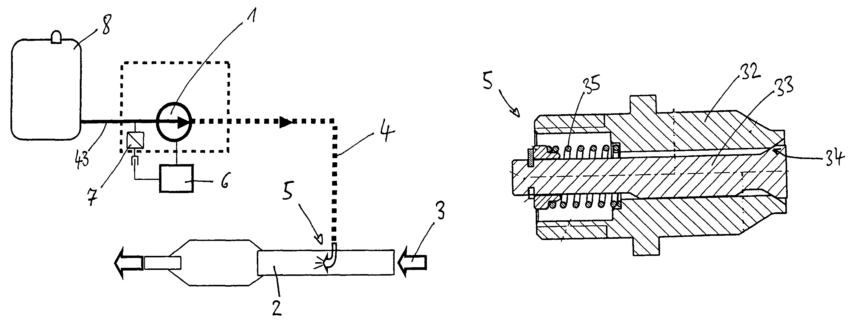
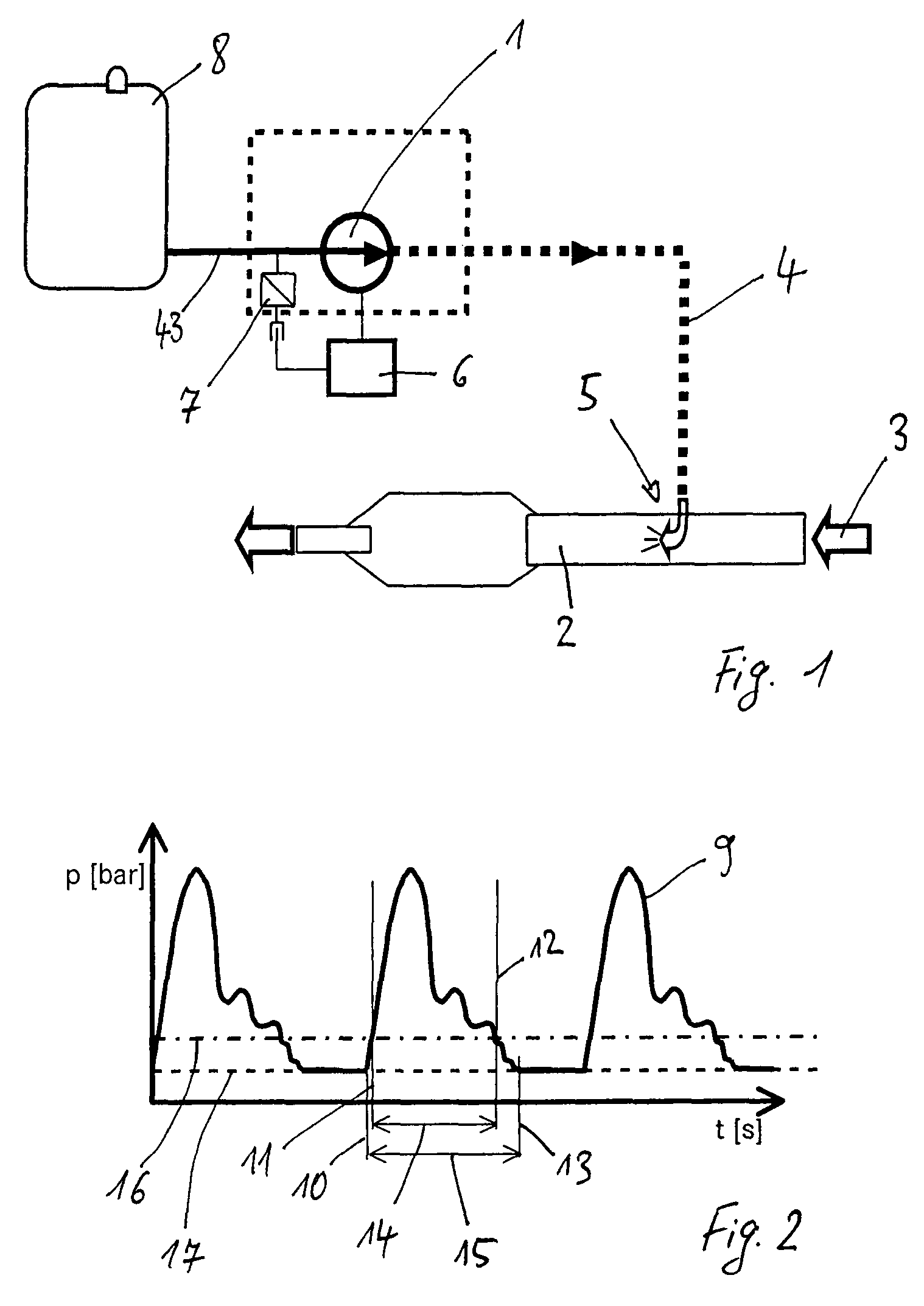
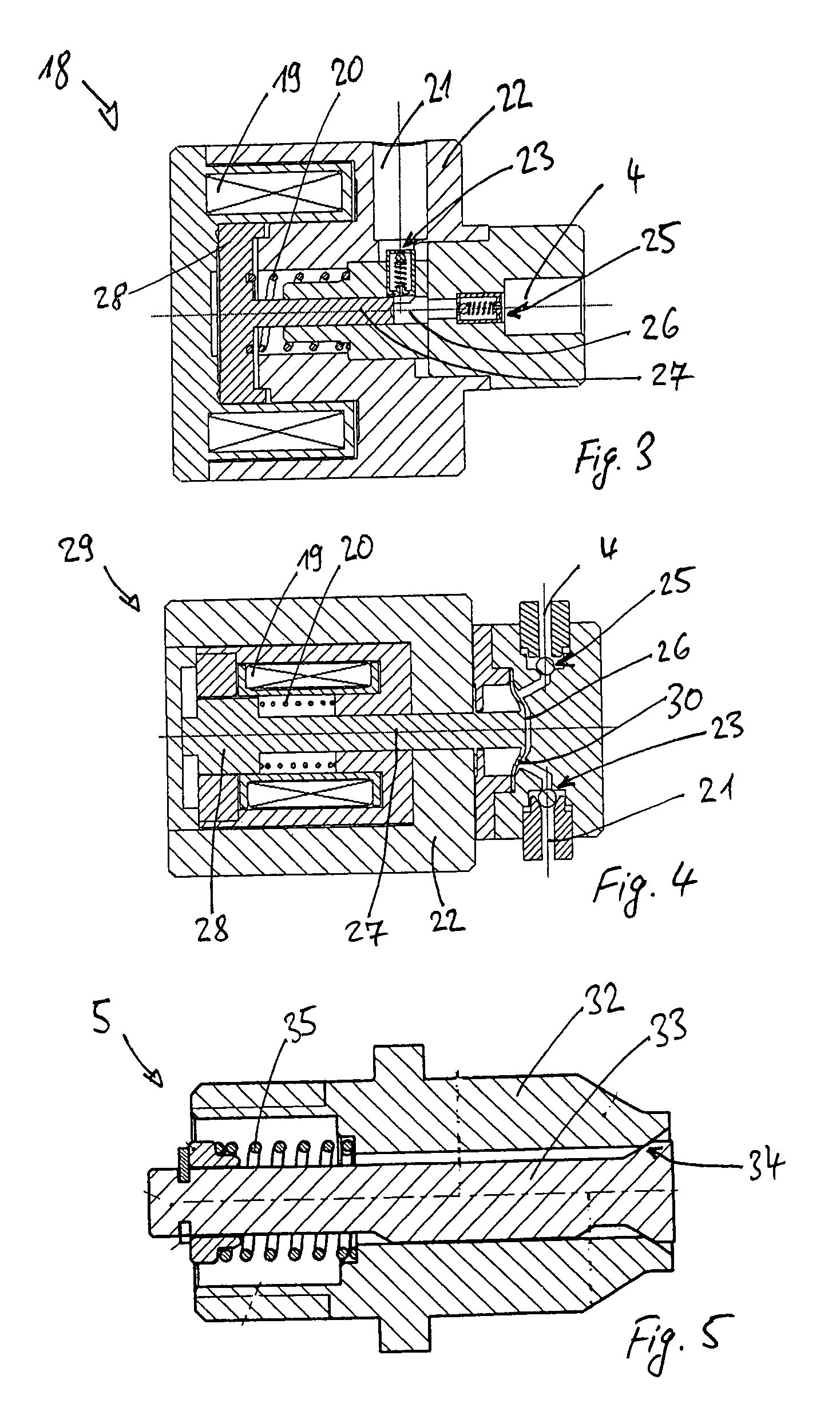
[0022]FIG. 1 shows schematically an arrangement for the dosed injection of a reducing agent. A pump 1 takes reducing agent 1 from a storage container 8 and pumps it via a high pressure line 4 and a nozzle 5 into an exhaust tract 2 through which the exhaust gas of an internal combustion engine which is not shown flows. The pump 1 is a piston pump 18 as shown in FIG. 3 or a membrane pump 29 as shown in FIG. 4. The pump 1 is a pumping unit and, at the same time, a dosing device. The nozzle 5 which is shown in detail in FIG. 5 has no dosing function but only serves to set the pressure level at which the reducing agent is injected. The pump 1 is controlled by a control unit which, depending on exhaust gas values and / or engine operating parameters, changes the operating frequency of the pump 1 and, as a result, the pumping volume while the pump stroke remains constant. To this end, a coil 19 cooperating with a magnet armature 28 is energized by corresponding current pulses. A temperature ...


PUM


Abstract

In an arrangement for the dosed injection of a reducing agent into the exhaust tract of an internal combustion engine, comprising a pump for the pulsed pumping of the reducing agent and an atomizing injection nozzle disposed in the exhaust tract of the internal combustion engine, the injection nozzle includes a valve element which opens and closes the injection nozzle depending on the pressure generated by the pump and permits the injection of the reducing agent into the exhaust tract only when the pressure of the reducing agent is in excess of a certain value in order to ensure proper atomization of any reducing agent injected into the exhaust tract.

Description

[0001]This is a Continuation-In-Part Application of pending International patent application PCT / EP2005 / 010815 filed Jul. 10, 2005 and claiming the priority of German patent application 10 2004 050 023.1 filed Oct. 13, 2004.BACKGROUND OF THE INVENTION[0002]The invention relates to an arrangement for the dosed injection of a reducing agent into the exhaust tract of an internal combustion engine, particularly of a diesel engine, using for example a piston pump for the pulsed delivery of the reducing agent to a nozzle extending into the exhaust tract of the engine.[0003]It is known to reduce the nitrogen oxide in the exhaust gas of internal combustion engines, particularly diesel engines, by selective catalytic reduction. To this end, an aqueous urea solution is injected into the exhaust tract finely atomized and in a dosed manner. For pressurizing the reducing agent generally a pump is used which supplies the reduction agent to a nozzle via which the reduction agent is injected into t...

Claims


Application Information

Patent Timeline
Patent Type & Authority Patents(United States)
IPC IPC(8): F01N3/00
CPCF01N3/2066F01N2610/02F01N2610/1473Y02T10/24Y02A50/20Y02T10/12F01N3/20F01N3/10
Inventor BAKAJ, LEOMALITSKY, WILHELM
Owner L'ORANGE GMBH
Learn More