Ring seal for a turbine engine

a technology for turbine engines and ring seals, which is applied in the direction of liquid fuel engines, vessel construction, marine propulsion, etc., can solve the problems of blade tip clearances that cannot be eliminated, blade tip clearances that can actually decrease, and loss in flow paths, so as to increase the efficiency of the turbine engine

Inactive Publication Date: 2011-01-18
SIEMENS ENERGY INC
View PDF25 Cites 28 Cited by
  • Summary
  • Abstract
  • Description
  • Claims
  • Application Information

AI Technical Summary

Benefits of technology

[0005]This invention relates to a turbine engine ring seal segment and ring seal for increasing the efficiency of the turbine engine by obstructing gas flow between a turbine engine ring seal segment and radially inward turbine blade tips. In particular, the turbine ring segment may include a turbine engine ring segment with an inner radial surface having a plurality of protrusions that induce vortices in gas flow along the length of the inner radial surface. The vortices create gas barriers that obstruct further gas flow between the blade tip and the turbine engine ring seal segment.
[0011]An advantage of this invention is that the efficiency of the turbine engine is increased.
[0013]Yet another advantage of this invention is that the coating can be abradable, and more particularly, the protrusions formed by the coating can be abradable.
[0015]Another advantage of this invention is that less of the gas flows through the tip gap and bypasses the blade, resulting in a decrease of tip losses and an increase in the efficiency of the overall turbine engine.
[0016]The presence of protrusions on the surface of the seal segment induces vorticity through at least two mechanisms. The first is to increase the form drag through the addition of roughness. The second enhancement is due to the presence of the protrusions changing the local velocity profile and hence the shear stress on the wall. This effect is related to the boundary layer thickness and the height and geometry of the protrusion or series of protrusions. The presence of a series of protrusions can result in small recirculation zones which act to choke the effective area and reduce freestream flow through the gap.

Problems solved by technology

Turbine engines commonly operate at efficiencies less than the theoretical maximum because, among other things, losses occur in the flow path as hot compressed gas travels down the length of the turbine engine.
Blade tip clearances cannot be eliminated because, during transient conditions such as during engine startup or part load operation, the rotating parts (blades, rotor, and discs) and stationary parts (outer casing, blade rings, and ring segments) thermally expand at different rates.
As a result, blade tip clearances can actually decrease during engine startup until steady state operation is achieved at which point the clearances can increase, thereby reducing the efficiency of the engine.
Although control systems have been developed to address the differences in blade tip clearance throughout the operational state of the turbine engine, inefficiencies still exist.

Method used


Image

  • Ring seal for a turbine engine
  • Ring seal for a turbine engine
  • Ring seal for a turbine engine

Examples


Embodiment Construction

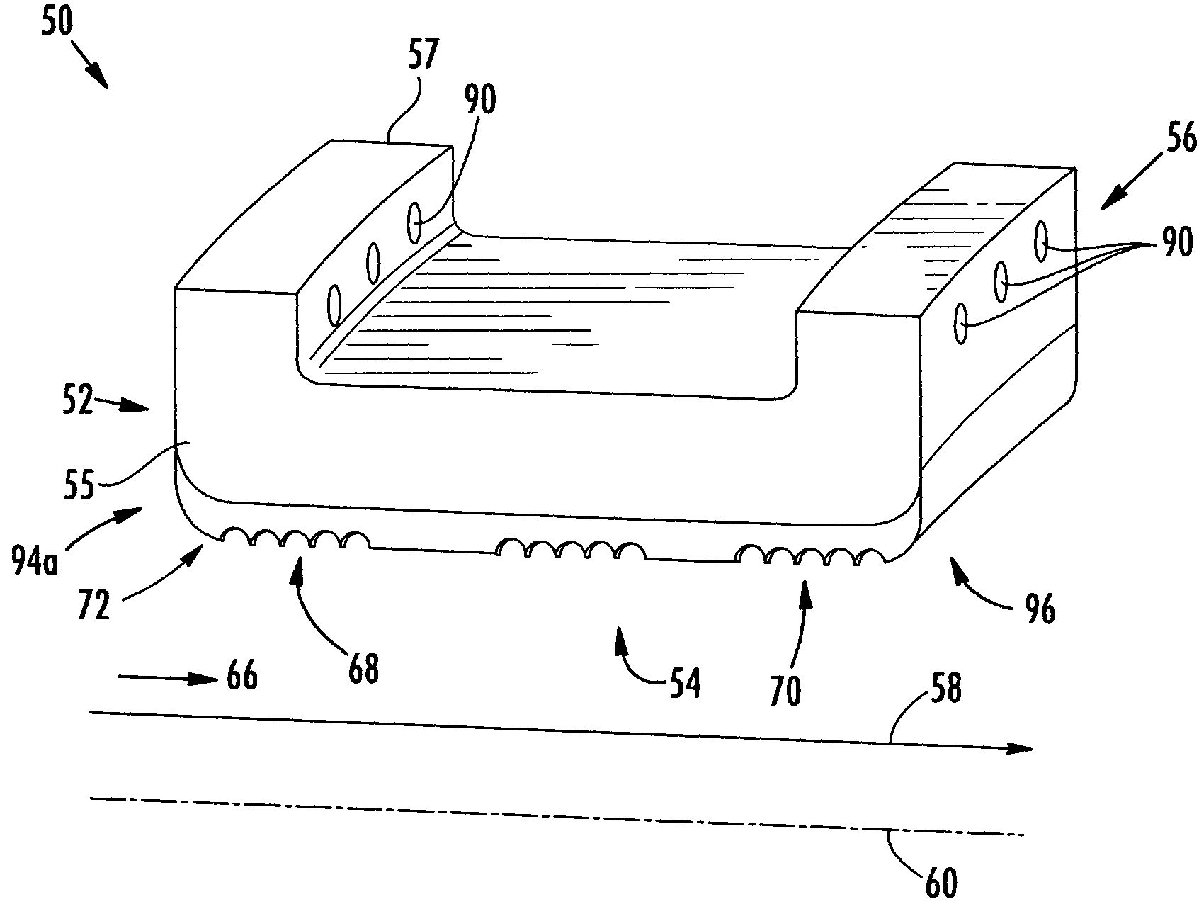
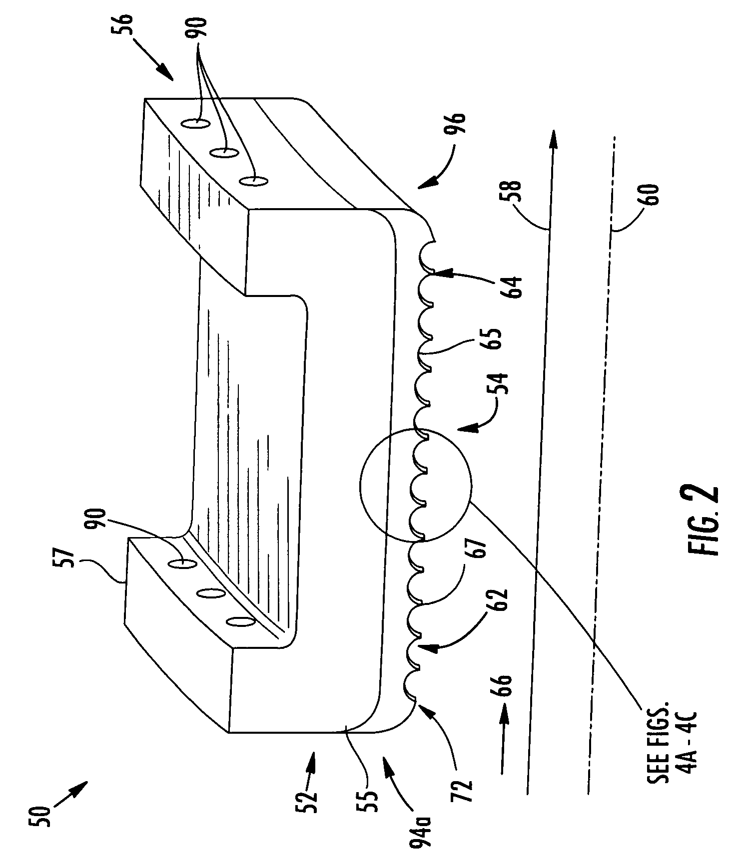
[0025]As shown in FIGS. 1-4C, this invention is directed to a ring seal 34 for a turbine engine. Aspects of the invention will be explained in connection with a ring seal 34, but the invention may be used in other seals. This invention relates to a turbine engine ring seal 34 for increasing the efficiency of the turbine engine by obstructing gas flow between a turbine engine ring seal segment 50 and radially inward turbine blade tips 26. In particular, the turbine ring segment 50 may include a turbine engine ring segment 50 with an inner radial surface having a plurality of protrusions that induce vortices in gas flow along the length of the inner radial surface. The vortices create gas barriers that obstruct further gas flow between the blade tip 26 and the turbine engine ring seal segment 50.

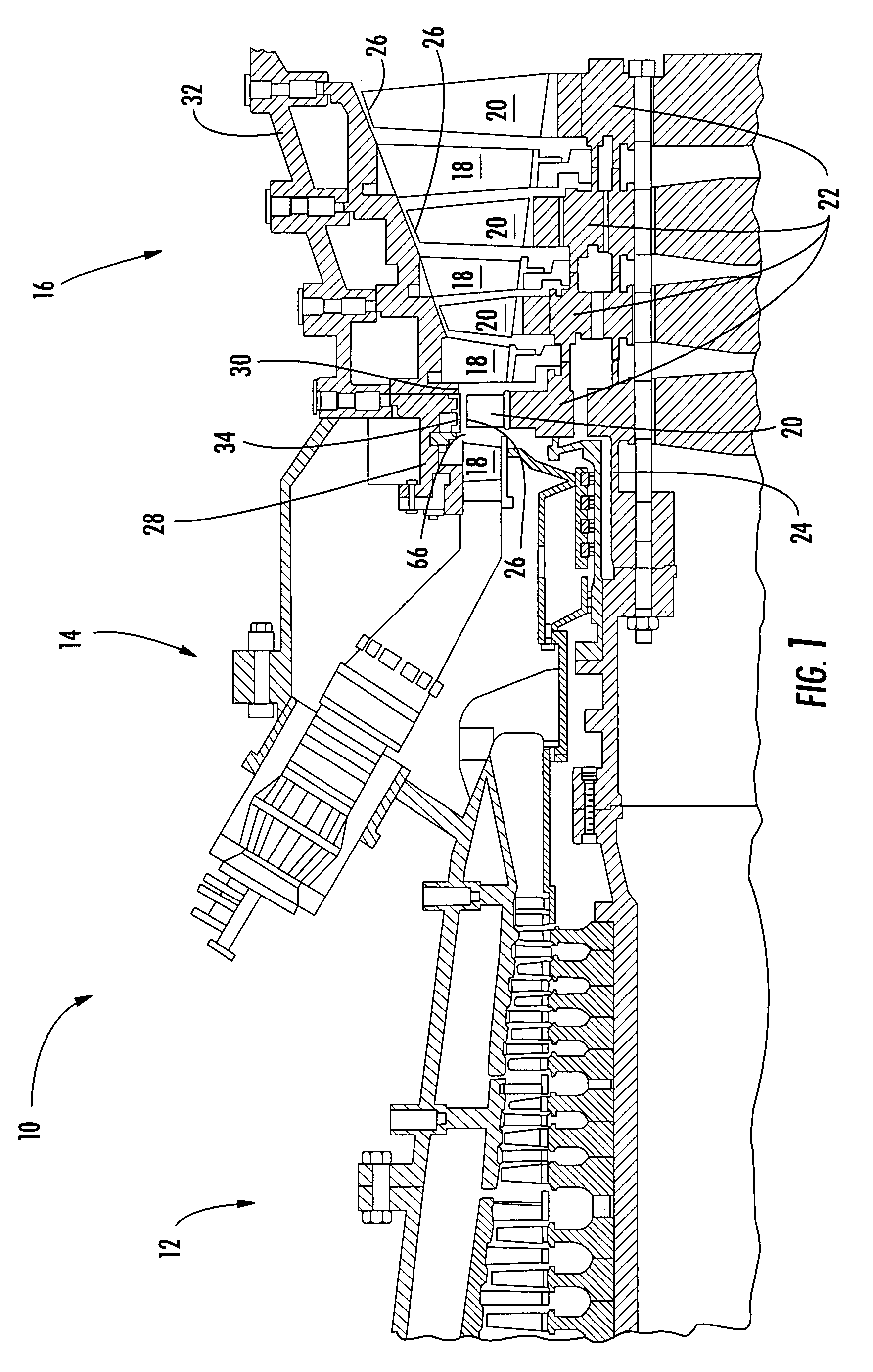
[0026]FIG. 1 shows an example of a turbine engine 10 having a compressor 12, a combustor 14 and a turbine 16. In the turbine section 16 of a turbine engine, there are alternating rows of stati...


PUM

PropertyMeasurementUnit
heightaaaaaaaaaa
heightaaaaaaaaaa
heightaaaaaaaaaa

Abstract

A turbine engine ring seal for sealing gaps between turbine engine outer seal segments and turbine blade tips. The turbine engine ring segment may have an inner radial surface that defines a portion of a gap gas flow path where the inner radial surface may be formed of an abradable ceramic coating and includes a plurality of gas flow protrusions that are oriented transverse to the gap gas flow path. The gas flow protrusions may induce vortices in the gas flow in the gap gas flow path. Additionally, the gas flow protrusions may be series of peaks and depressions between two adjacent peaks, where the depressions have an approximate semicircular shape. The distance between two adjacent peaks may be equal or greater than a width of the depression and the height of a single peak may be six percent or greater than the distance between two adjacent peaks.

Description

FIELD OF THE INVENTION[0001]This invention is directed generally to turbine engine ring seals and turbine engine ring segments thereof, and more particularly to the inner radial surface of turbine engine ring segments.BACKGROUND[0002]Turbine engines commonly operate at efficiencies less than the theoretical maximum because, among other things, losses occur in the flow path as hot compressed gas travels down the length of the turbine engine. One example of a flow path loss is the leakage of hot combustion gases across the tips of the turbine blades where work is not exerted on the turbine blade. This leakage occurs across a space between the tips of the rotating turbine blades and the surrounding stationary structure, such as ring segments that form a ring seal. This spacing is often referred to as the blade tip clearance.[0003]Blade tip clearances cannot be eliminated because, during transient conditions such as during engine startup or part load operation, the rotating parts (blade...

Claims


Application Information

Patent Timeline
Patent Type & Authority Patents(United States)
IPC IPC(8): F01D11/12
CPCF01D11/122F05D2240/11F05D2250/70F05D2250/71F05D2260/30F05D2240/127F05D2230/31F05D2250/711F05D2300/21F05D2230/90
Inventor MARINI, BONNIE D.KELLER, DOUGLAS A.
Owner SIEMENS ENERGY INC
Why Eureka
Try Eureka