Detecting a disturbance in the propagation of light in an optical waveguide

a technology of optical waveguide and propagation mode, which is applied in the direction of optical apparatus testing, structural/machine measurement, instruments, etc., can solve the problems of interfering with the overall intensity of backscattered light, and achieve the effect of accurately detecting disturbances, accurate resolution, and effective detection of disturbances

Active Publication Date: 2011-01-18
VIAVI SOLUTIONS INC
View PDF11 Cites 46 Cited by
  • Summary
  • Abstract
  • Description
  • Claims
  • Application Information

AI Technical Summary

Benefits of technology

[0012]The applicants have recognised that such a light pulse, which might be referred to as a “composite light pulse”, can allow more effective detection of disturbances in the propagation of light in the waveguide. More specifically, localised differences in the rate of change of phase of light between successive light pulses travelling along the waveguide can be more accurately detected.
[0013]As the two sections of higher intensity of the pulse are coherently related, light backscattered from each of the two sections can interfere to contribute to the overall intensity of backscattered light. This interference depends on the phase between light backscattered from each of the sections of higher intensity of the light pulse. However, as the sections of higher intensity are separated from one another by a section of lower or substantially zero intensity, little or no light is backscattered from this section of the light pulse. With appropriate signal processing, differences in the phase between light backscattered from each of the two sections of higher intensity can therefore be resolved in the absence of or with very little contribution from light backscattered from within the section of lower or substantially zero intensity. So, differences in the rate of change of phase of light travelling along the waveguide in the section of lower intensity of the pulse can be accurately resolved.
[0014]Furthermore, sensitivity to phase disturbances can be controlled by varying the length of the section of lower or substantially zero intensity. Indeed, it is preferred that the apparatus comprises means for selecting the length of the section of lower or substantially zero intensity. Similarly, the method may comprise selecting the length of the section of lower or substantially zero intensity. Longer sections of lower intensity can provide increased sensitivity.
[0016]The apparatus preferably has a photodetector for generating a signal representing a time distributed intensity of light backscattered in the waveguide as the light pulse travels along the waveguide. Ideally, the photodetector should be able to detect all of the frequencies present in the coherently backscattered light. It is also useful for the backscattered light to be averaged over a period around equal to the duration (e.g. temporal extent at a single point) of one of the sections of higher intensity of the light pulses. The photodetector can therefore conveniently have a response time approximately equal to the duration of each of the shorter section of higher intensity of the light pulse.
[0025]enhancing the signal in respect to noise due to variations in backscatter amplitudes by normalising to undisturbed values.
[0026]The signal may be enhanced in respect of noise due to variations in the amplitude and phase of the backscatter by employing a coherent-pulse shape which allows detection and resolution of the scatter structure within the pulse, and a suitable averaging and normalisation of the resulting signal structure.

Problems solved by technology

As the two sections of higher intensity of the pulse are coherently related, light backscattered from each of the two sections can interfere to contribute to the overall intensity of backscattered light.

Method used


Image

  • Detecting a disturbance in the propagation of light in an optical waveguide
  • Detecting a disturbance in the propagation of light in an optical waveguide
  • Detecting a disturbance in the propagation of light in an optical waveguide

Examples


Embodiment Construction

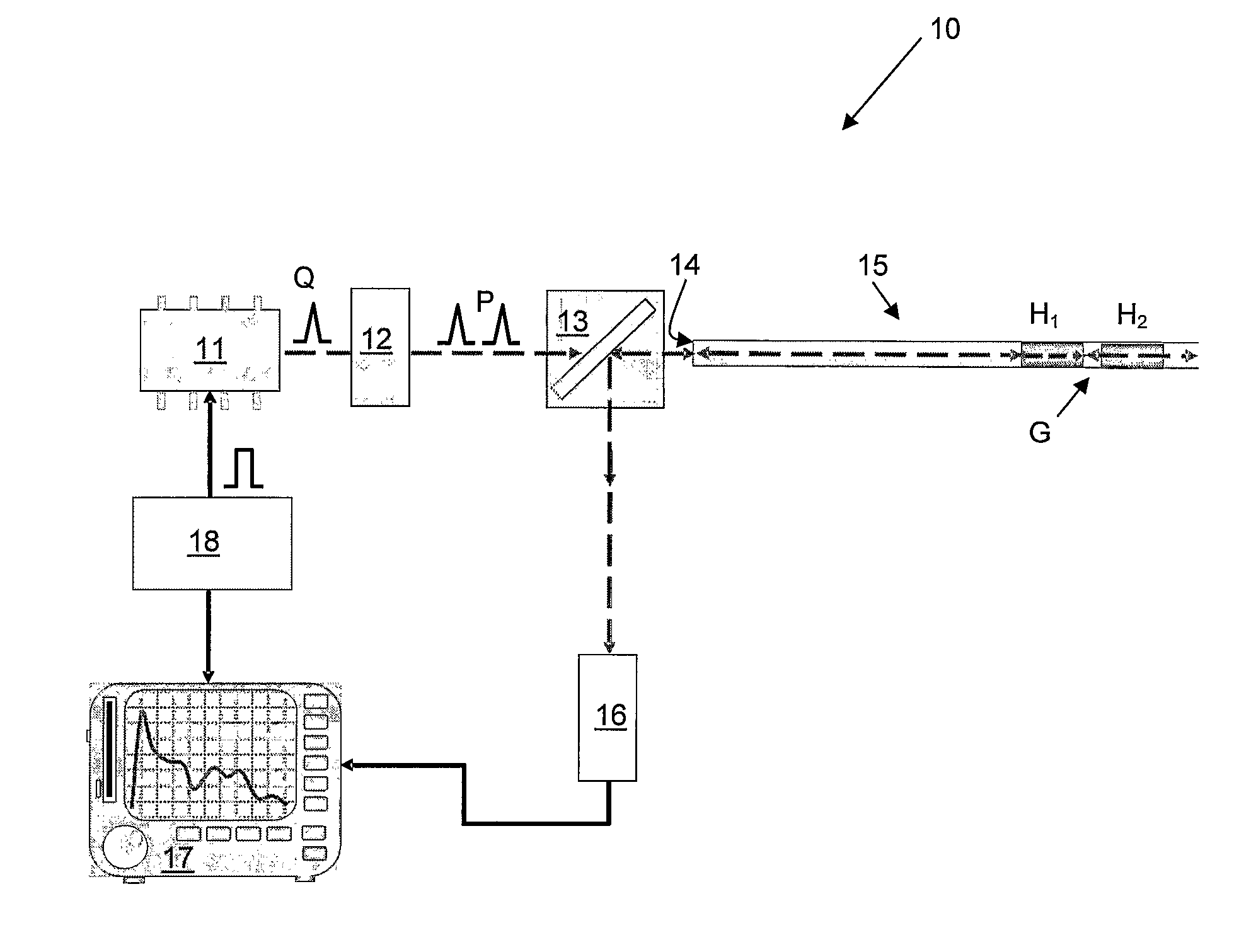
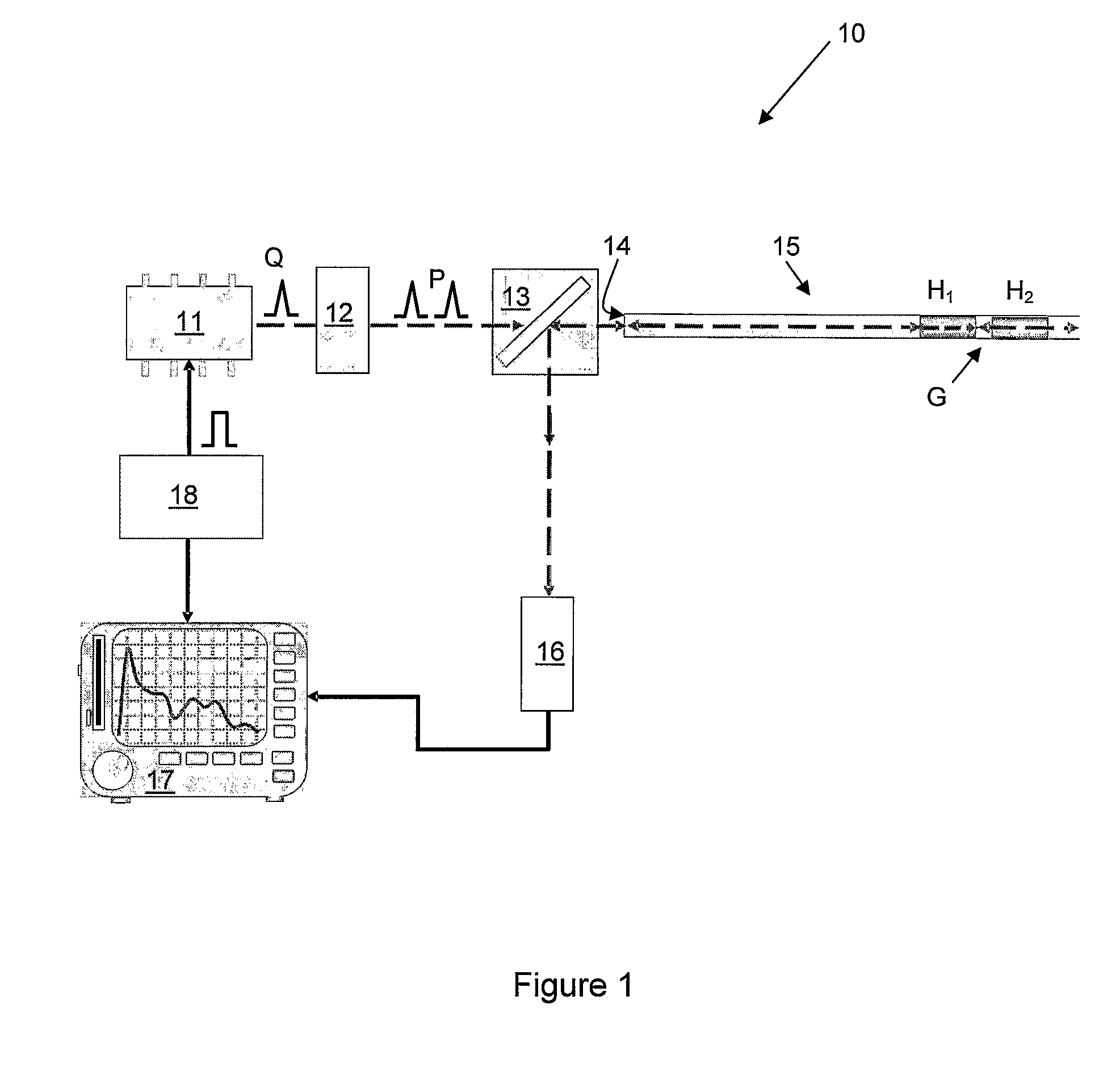
[0031]Referring to FIG. 1, an optical time domain reflectometry apparatus 10 has a laser 11 for producing light Q. The laser 11 is arranged to output the light Q it produces to a light modulator 12 for modulating the light Q to produce light pulses P. The light pulses P produced by the light modulator 12 each have two sections H1, H2 of higher intensity separated by a gap G of lower intensity. Indeed, in this embodiment, the gap G of lower intensity has substantially zero intensity and each of the sections H1, H2 of higher intensity are effectively individual pulses of light, except that they are substantially mutually coherent, as described below in more detail. The light modulator 12 is adapted to vary the duration of the gap G of lower intensity of the light pulses to vary the resolution of the apparatus 10. A smaller gap G can provide increased resolution. In another embodiment, the light modulator 12 provides a first of the two sections H1, H2 of higher intensity and the second...


PUM

PropertyMeasurementUnit
distancesaaaaaaaaaa
distancesaaaaaaaaaa
distancesaaaaaaaaaa

Abstract

An optical time domain reflectometry apparatus has a laser and light modulator for producing coherent light pulses, each having two sections of higher intensity separated by a gap of lower or substantially zero intensity. As the light pulses propagate along the optical fibre, light is continuously Rayleigh backscattered by inhomogeneities of the optical fibre. A photodetector generates backscatter signals representing the intensity of light Rayleigh backscattered in the optical fibre as each light pulse travels along the optical fibre. The PC uses these backscatter signals to derive a difference signal representing a change dI in intensity between signals generated from two successive pulses. The PC then calculates the Root Mean Square (RMS) of the difference signal averaged over the interval between the two sections of the light pulses. Next, the PC averages the backscatter signal generated from the first of the pulses over the same interval and normalises the RMS difference signal using the averaged signal to obtain a compensated difference signal that depends only on differences in the rate of change of phase of light of the light pulses as they travelled along the waveguide. This is repeated at different wavelengths to allow the compensated difference signal to be adjusted to represent the magnitude of the differences.

Description

CROSS REFERENCE TO RELATED APPLICATIONS[0001]The present application is a National Phase Application of International Application No. PCT / GB2005 / 004243, filed Nov. 3, 2005, which claims priority to Great Britain Patent Application No. 0424305.1, filed Nov. 3, 2004, which applications are incorporated herein fully by this reference.FIELD OF THE INVENTION[0002]This invention relates to an apparatus and method for detecting a disturbance in the propagation of light in an optical waveguide. More particularly, but not exclusively, the invention relates to improvements to Optical Time-Domain Reflectometry (OTDR) for detecting an externally induced disturbance in the phase of light propagating in a monomode optical fibre.BACKGROUND TO THE INVENTION[0003]OTDR is an established technique for analysing the propagation of light in an optical fibre. In the telecommunications industry, the technique is widely used to detect and locate damage to optical fibres. The intensity of light backscattere...

Claims


Application Information

Patent Timeline
Patent Type & Authority Patents(United States)
IPC IPC(8): G01N21/00G01M11/00
CPCG01M11/3118G01M11/3127
Inventor ROGERS, ALAN JOHNKANELLOPOULOS, SOTIRIS EMILSHATALIN, SERGEY VLADIMIR
Owner VIAVI SOLUTIONS INC
Why Eureka
Try Eureka