Autonomous machine

a technology of autonomous machines and working areas, applied in the direction of electric programme control, program control, instruments, etc., can solve the problems of requiring supervision or a specially prepared working area, and difficulty in realizing the effect of working areas

Inactive Publication Date: 2011-01-18
DYSON TECH LTD
View PDF34 Cites 53 Cited by
  • Summary
  • Abstract
  • Description
  • Claims
  • Application Information

AI Technical Summary

Benefits of technology

[0007]The present invention seeks to provide an autonomous machine of the kind which performs a task which requires

Problems solved by technology

Machines of this type have the disadvantage of requiring supervision or a specially prepared working area.
Autonomous machines of this kind can cope very well with simple working areas, e.g. rooms with a

Method used


Image

  • Autonomous machine
  • Autonomous machine
  • Autonomous machine

Examples


Embodiment Construction

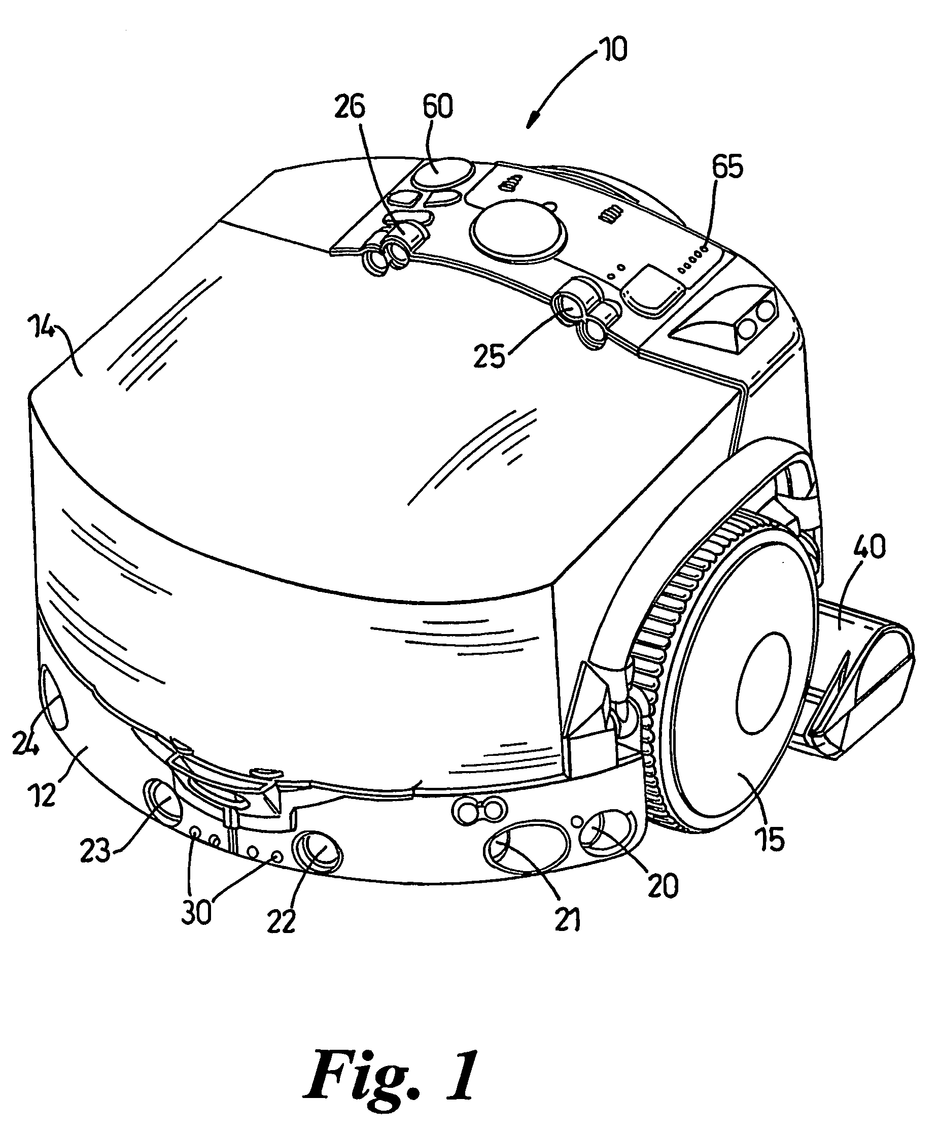
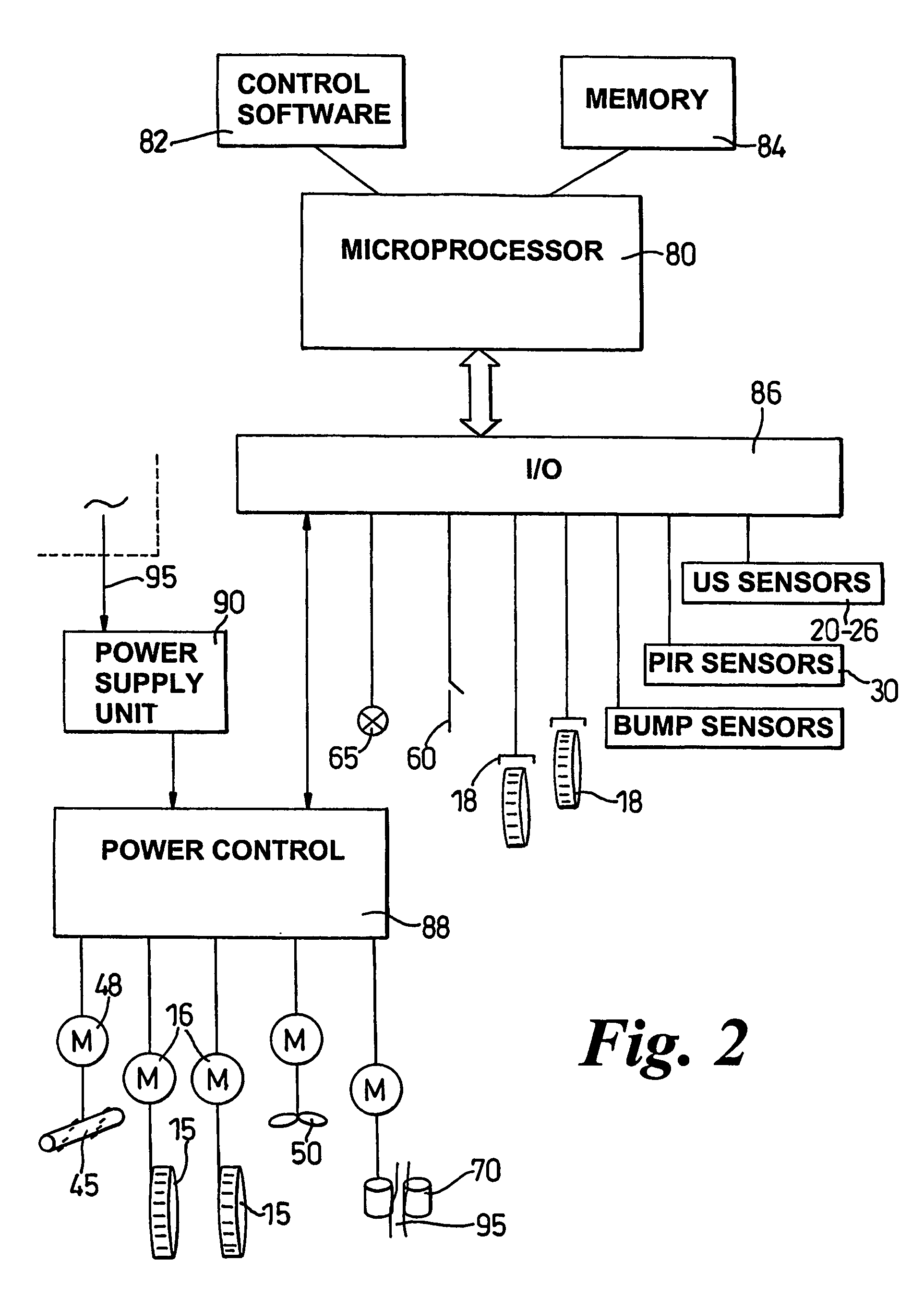
[0026]FIG. 1 of the drawings shows a robotic, or autonomous, floor cleaning machine in the form of a robotic vacuum cleaner 10. FIG. 2 shows the electrical systems incorporated into the vacuum cleaner 10.

[0027]The machine comprises a main body or supporting chassis 12, two driven wheels 15, a cleaner head 40, a user interface with buttons 60 and indicator lamps 65 and various sensors 20-26, 30 for sensing the presence of objects around the machine. Also mounted on the chassis 12 is apparatus 14 for separating dirt, dust and debris from an incoming airflow and for collecting the separated material, a reel for storing a length of power cable, and a system for dispensing and rewinding the power cable. The machine 10 is supported on the two driven wheels 15 and a castor wheel (not shown) at the rear of the machine. The driven wheels 15 are arranged at either end of a diameter of the chassis 12, the diameter lying perpendicular to the longitudinal axis of the cleaner 10. The driven wheel...


PUM


Abstract

A control system is provided for navigating an autonomous machine around a working area in a manner that causes the machine to traverse substantially all of the free surface of the working area. The control system is arranged to cause the machine to follow a boundary of the working area and to perform a plurality of movements, each movement comprising the machine travelling away from the boundary of the working area, at an angle to the boundary, and returning again to the boundary. The machine moves along the boundary of the working area between each movement and repeats the movements as the machine follows substantially the entire boundary of the working area.

Description

FIELD OF THE INVENTION[0001]This invention relates to an autonomous machine for performing a task which requires the machine to traverse substantially all of an area. The invention is particularly suitable for, but not limited to, an autonomous surface treating machine such as an autonomous vacuum cleaner, for cleaning a room of a building.BACKGROUND OF THE INVENTION[0002]There have been various proposals to provide autonomous or robotic machines for performing duties such as cleaning or polishing a floor area, or for mowing grass. In their simplest form, the machine requires a training phase during which the machine is manually led around the area in which it is to work. Following this training phase, the machine will then perform the required work as it follows the path which it stored in its memory during the training phase. Other machines may simply follow a predetermined route which is marked by means such as a cable which is buried beneath the working area. Machines of this ty...

Claims


Application Information

Patent Timeline
IPC IPC(8): G05B19/18G05B19/04G05D1/02
CPCG05D1/0227G05D1/0219G05D2201/0215G05D1/0274G05D1/0272A61L2202/16B60L2200/40B60L9/00A47L9/00G05D1/021
Inventor ALDRED, MICHAEL DAVIDBOMMER, ALEXANDER PHILIP
Owner DYSON TECH LTD
Why Eureka
Try Eureka