Gas sensor with at least one catalytic measuring element

a technology of catalytic measuring element and gas sensor, which is applied in the direction of chemical analysis using combustion, chemical analysis using sonic/ultrasonic/infrasonic waves, and material thermal analysis, etc. it can solve the problems of poor sensitivity of the correspondingly covered gas sensor, poor diffusion of gas to be measured, and obvious drawbacks, so as to improve the gas exchange with the environment, improve the effect of gas exchange and easy exit of the combustion chamber

Active Publication Date: 2011-01-25
DRAGER SAFETY
View PDF14 Cites 8 Cited by
  • Summary
  • Abstract
  • Description
  • Claims
  • Application Information

AI Technical Summary

Benefits of technology

[0007]The object of the present invention is, in particular, to make available a gas sensor with at least one catalytic measuring element, which gas sensor is less sensitive to temperature changes, on the one hand, and, on the other hand, additionally ensures a good gas exchange with the environment while shock resistance is improved at the same time.
[0010]Combustion products as a consequence of the controlled catalytic combustion can leave the combustion chamber more easily, as a consequence of which gas exchange with the environment is improved and at the same time there is a good fresh gas supply to the measuring elements. Better gas exchange also means that the measuring sensitivity for gases and vapors to be measured is improved, so that the signal-to-noise ratio is improved as well.

Problems solved by technology

An essential drawback of this arrangement is the poorer diffusion of the gas to be measured compared to the prior-art arrangements with support wires and catalytic measuring elements arranged thereon, i.e., especially heat tone sensors called Pellistors.
The drawbacks become obvious especially in case of measuring high-boiling gases such as nonane or xylene.
This is due both to the response time and the sensitivity of the correspondingly covered gas sensors being markedly poorer than without a cover.

Method used


Image

  • Gas sensor with at least one catalytic measuring element
  • Gas sensor with at least one catalytic measuring element
  • Gas sensor with at least one catalytic measuring element

Examples


Embodiment Construction

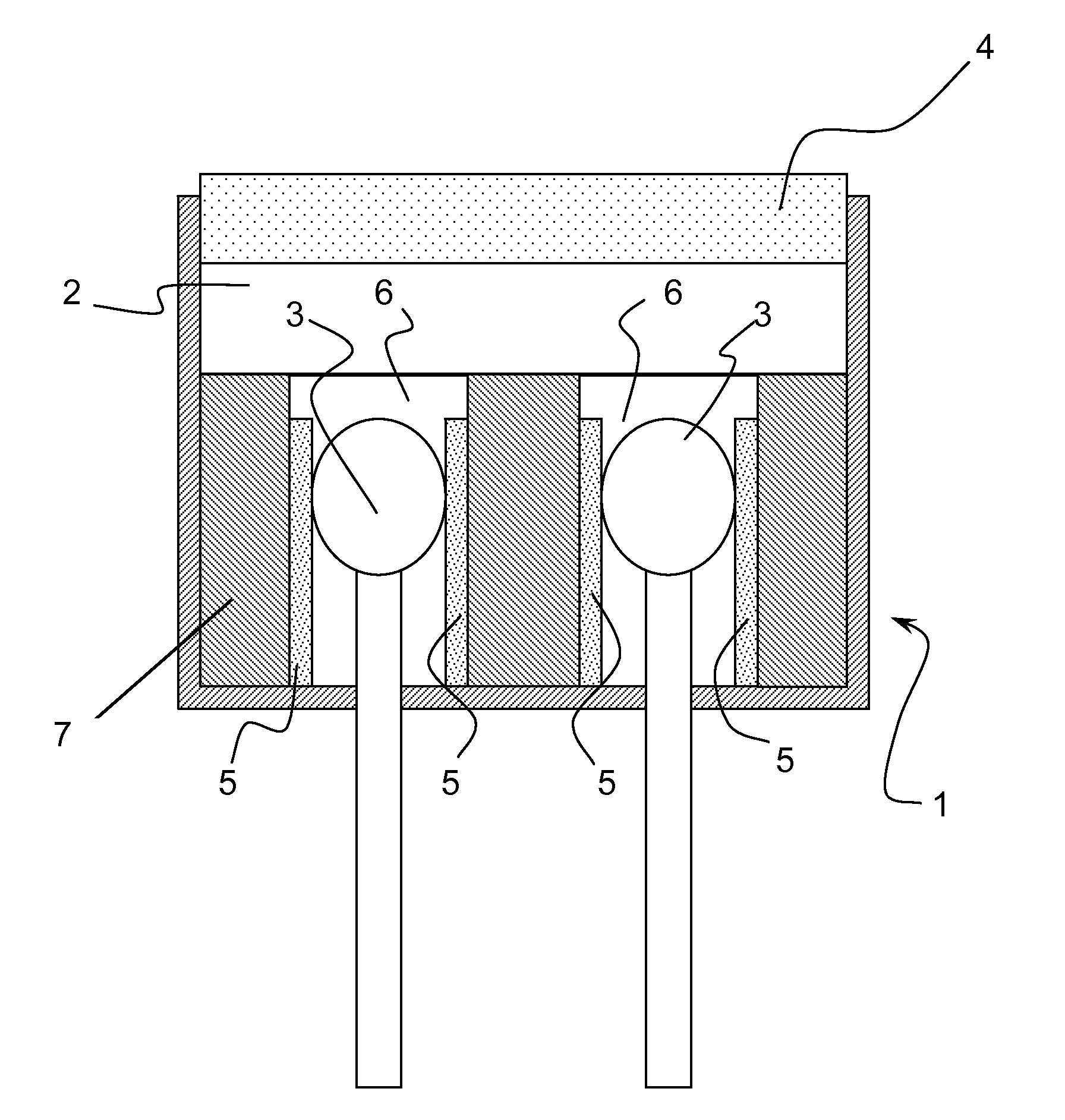
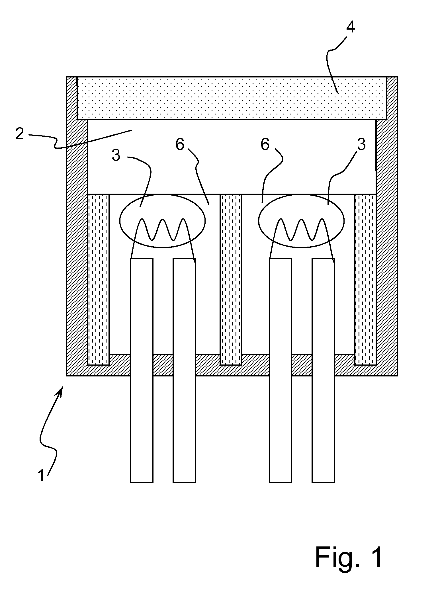
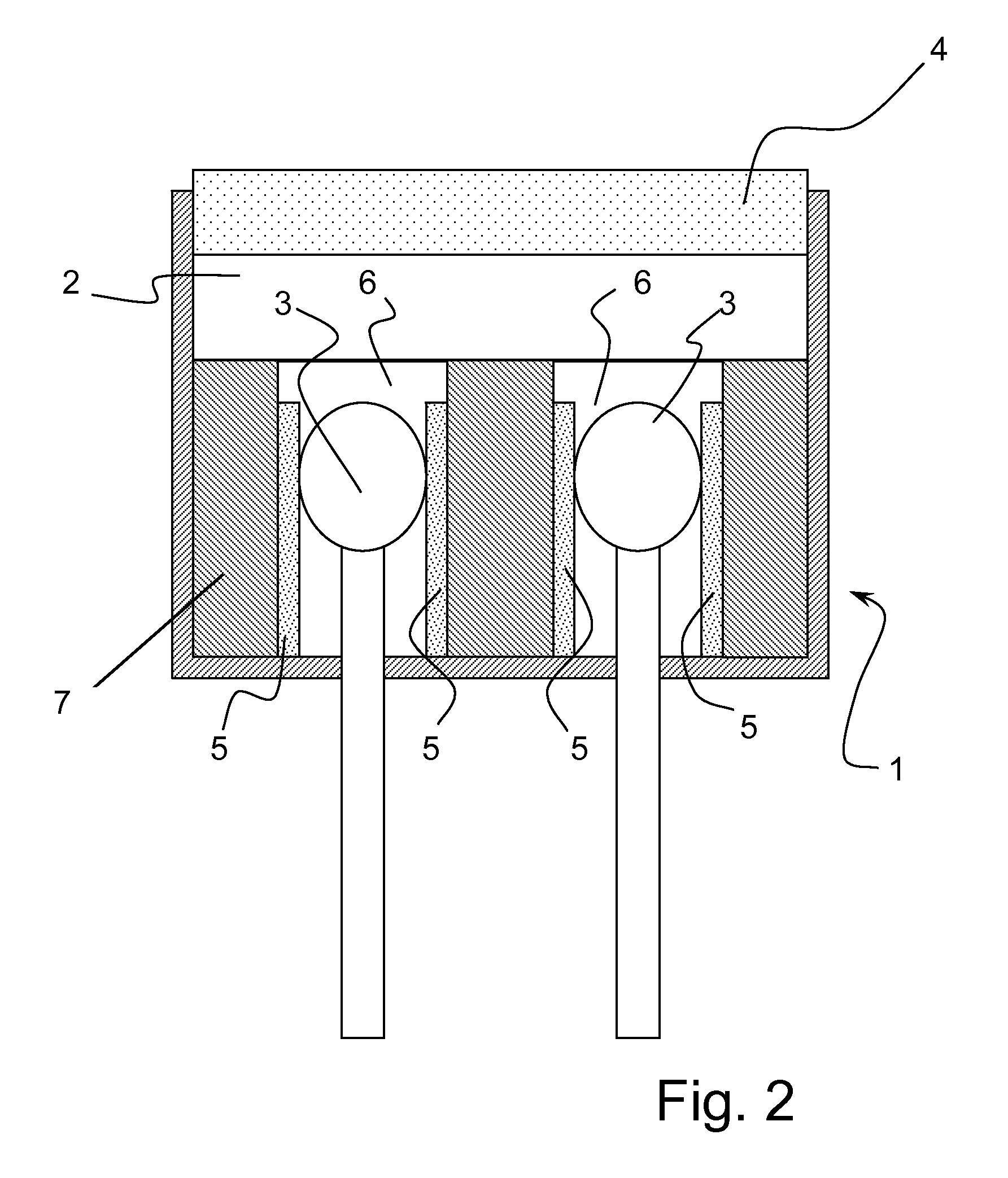
[0021]Referring to the drawings in particular, two measuring elements 3 designed as Pellistors are located in the preferably metallic sensor housing 1 with the housing opening element 4 made as a gas-permeable metallic or ceramic sintered element for the gas exchange with the environment. Only one of the otherwise identical measuring elements 3 is provided with a catalyst characteristic of the controlled combustion of the gas or gases to be measured. The sintered element 4 is used at the same time as a flame arrester and may also consist of a wire cloth. The metallic or ceramic sintered gas-permeable housing opening element 4 may be an explosion protection element. The explosion protection element may comprise a metallic grid.

[0022]A Pellistor is used in one of the two measuring elements 3 (the catalytic measuring element) for the catalytic oxidation to detect the gas or gases to be measured. The other, otherwise identical Pellistor without catalyst (another measuring element 3) is ...


PUM

PropertyMeasurementUnit
densityaaaaaaaaaa
thicknessaaaaaaaaaa
thicknessaaaaaaaaaa

Abstract

A gas sensor has shock resistance and temperature resistance attributes. The gas sensor includes at least one catalytic measuring element (3), which is arranged in a sensor housing (1) forming a combustion chamber (2). The sensor housing (1) has at least one gas-permeable housing opening (4) for the gas exchange between the environment and the combustion chamber (2). The catalytic measuring element (3) is arranged between at least two disk-shaped support elements (5) made of a heat-insulating and temperature-resistant material.

Description

CROSS REFERENCE TO RELATED APPLICATIONS[0001]This application claims the benefit of priority under 35 U.S.C. §119 of German Patent Application DE 10 2007 032 700.7 filed Jul. 13, 2007, the entire contents of which are incorporated herein by reference.FIELD OF THE INVENTION[0002]The present invention pertains to a gas sensor with at least one catalytic measuring element.BACKGROUND OF THE INVENTION[0003]A gas sensor with a heated gas-sensitive semiconductor as a measuring element is disclosed in DE 38 10 409 A1. The measuring element is embedded according to this document directly in a gas-permeable, heat-insulating cover in order to reduce the release of heat and to reduce the energy consumption in this manner. In addition, the sensor as a whole is said to be stabilized and made largely insensitive to mechanical effects such as shocks.[0004]An essential drawback of this arrangement is the poorer diffusion of the gas to be measured compared to the prior-art arrangements with support w...

Claims


Application Information

Patent Timeline
Patent Type & Authority Patents(United States)
IPC IPC(8): G01N7/00G01N33/00G01N27/00G01N31/00G01N21/00
CPCG01N27/16Y10T436/21Y10T436/14G01N33/0027
Inventor SCHLICHTE, MLADENSTENDER, ERIK
Owner DRAGER SAFETY
Why Eureka
Try Eureka