
Alignment changing control device

a control device and a technology of a control device, applied in the direction of electric energy management, non-deflectable wheel steering, underwater vessels, etc., can solve the problems of inability to optimize the operation of electric actuators, motor burnout, and difficulty in precisely measuring the temperatur

Inactive Publication Date: 2011-02-01
HONDA MOTOR CO LTD
View PDF51 Cites 21 Cited by
  • Summary
  • Abstract
  • Description
  • Claims
  • Application Information

AI Technical Summary

Benefits of technology

Precise temperature estimation and power management prevent motor burnout, optimize actuator operation, and reduce hardware complexity and costs by using vehicle speed and air temperature corrections, and storing temperatures in nonvolatile memory for accurate restarts.

Problems solved by technology

However, if the temperature sensor is attached to the main body of the motor, noises caused by the motor and the like will be brought into the output signal of the temperature sensor, therefore it becomes difficult to precisely measure the temperature.
For this reason, when restarting the vehicle and driving the motor shortly after cutting off the power supplied to the motor of the electric actuator while the temperature of the motor is high, a temperature difference is generated between the actual temperature of the motor and the estimated temperature of the motor estimated by the controlling circuit using the initial value, therefore there is a concern that the motor might be burn out.
Hei 4-71379 is applied to an electric actuator installed to a moving object such as the vehicle in a state exposed to the outside-air, since the flow of air around the electric actuator is not taken into consideration, the estimated temperature of the motor is higher than the actual temperature of the motor, and therefore the operation of the electric actuator can not be optimally limited, and the optimum electric actuator can not be selected.
Hei 6-247324, since it is necessary to provide hardware for calculating the cutting off time and to newly provide an internal battery within the motor control device, the motor control device will have a complicated structure and high cost.

Method used


Image

  • Alignment changing control device
  • Alignment changing control device
  • Alignment changing control device

Examples


Embodiment Construction

)

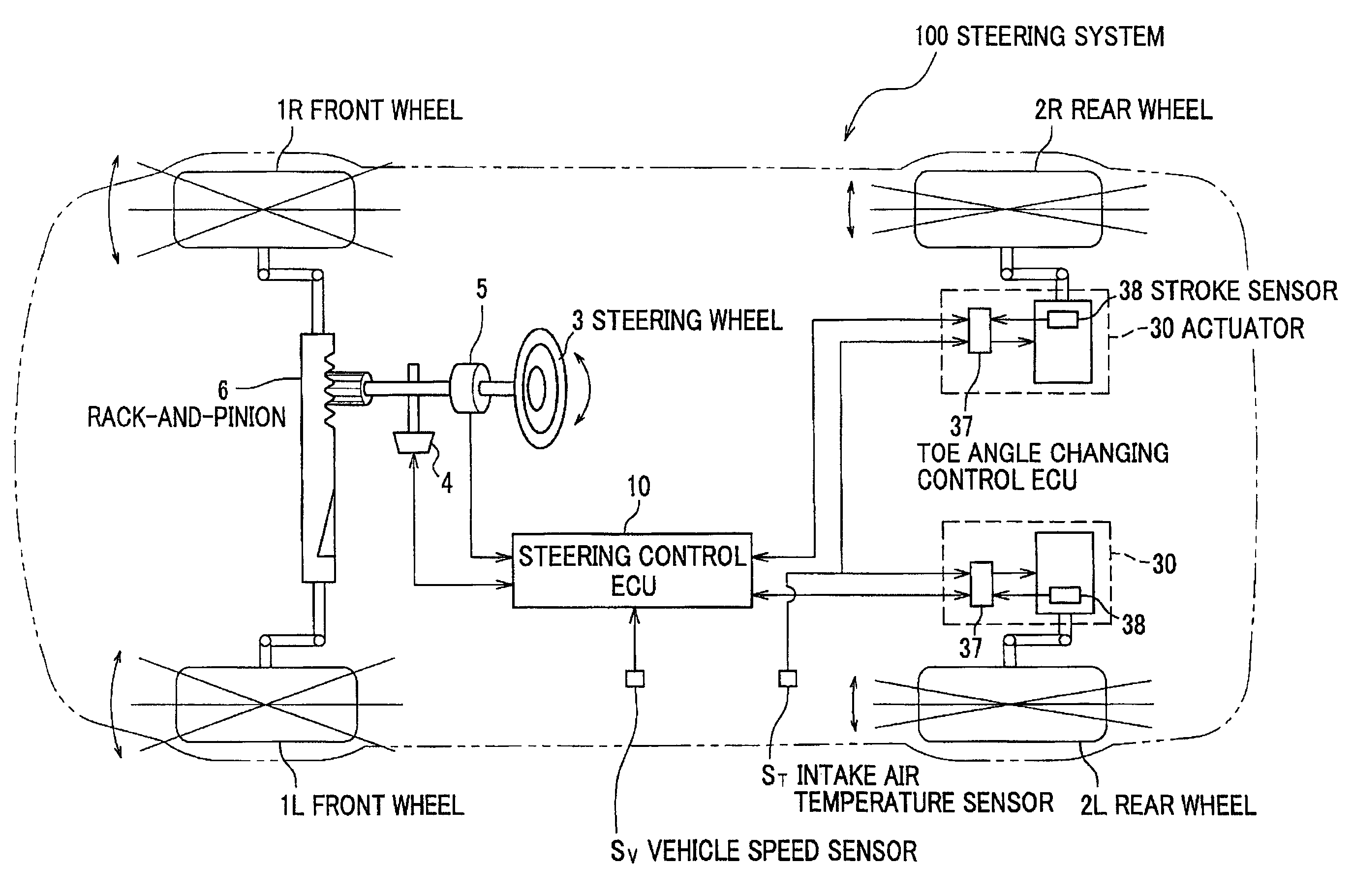
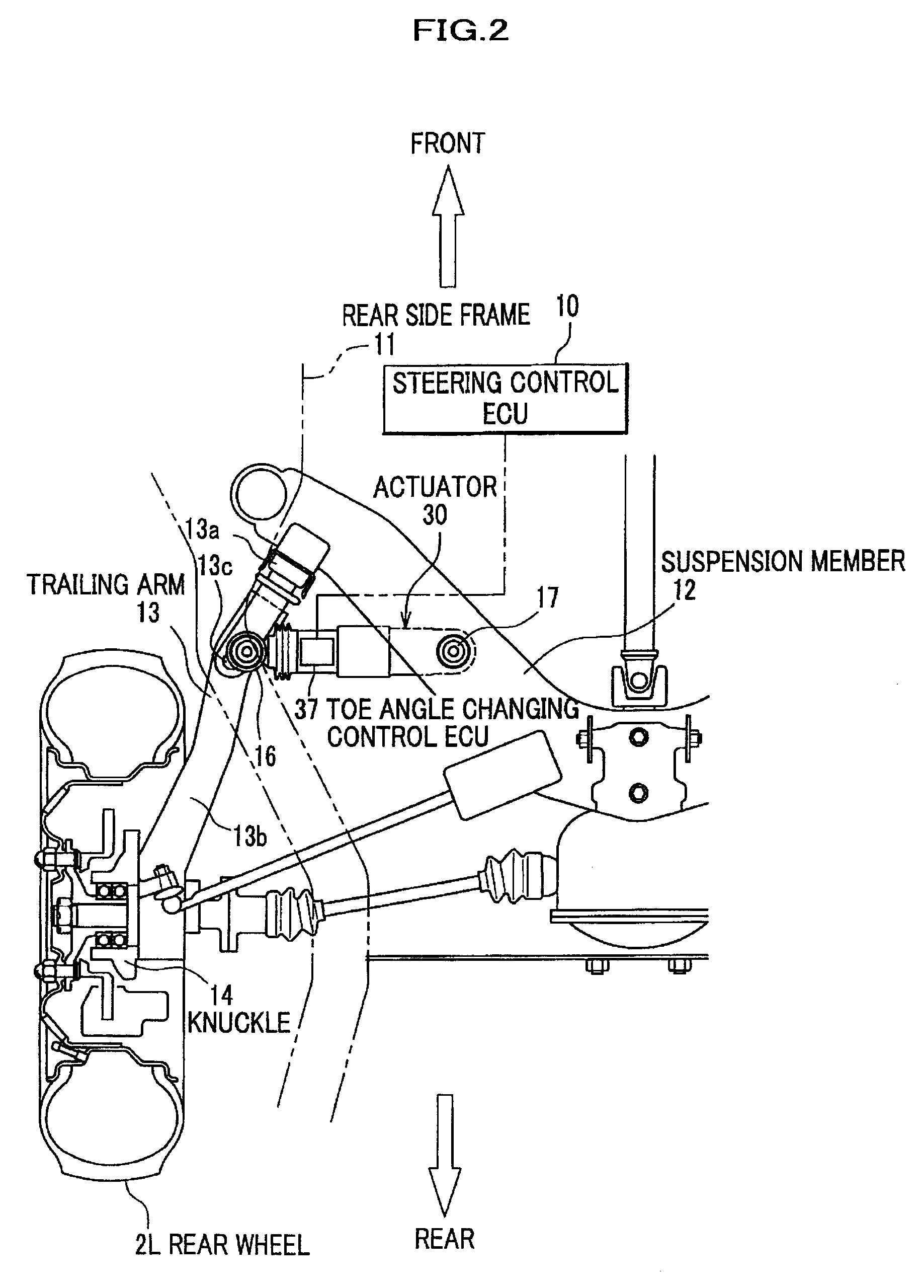
[0036]The preferred embodiment (referred to as “embodiment” hereinafter) will be described below with reference to the attached drawings. In the present embodiment, an alignment changing control device according to the present invention is explained by using an example in which the alignment changing control device is a toe angle changing control ECU for controlling the operation of an electric actuator (referred to as “actuator” hereinafter) which changes the toe angle of rear wheels of a vehicle.

[0037](Steering System)

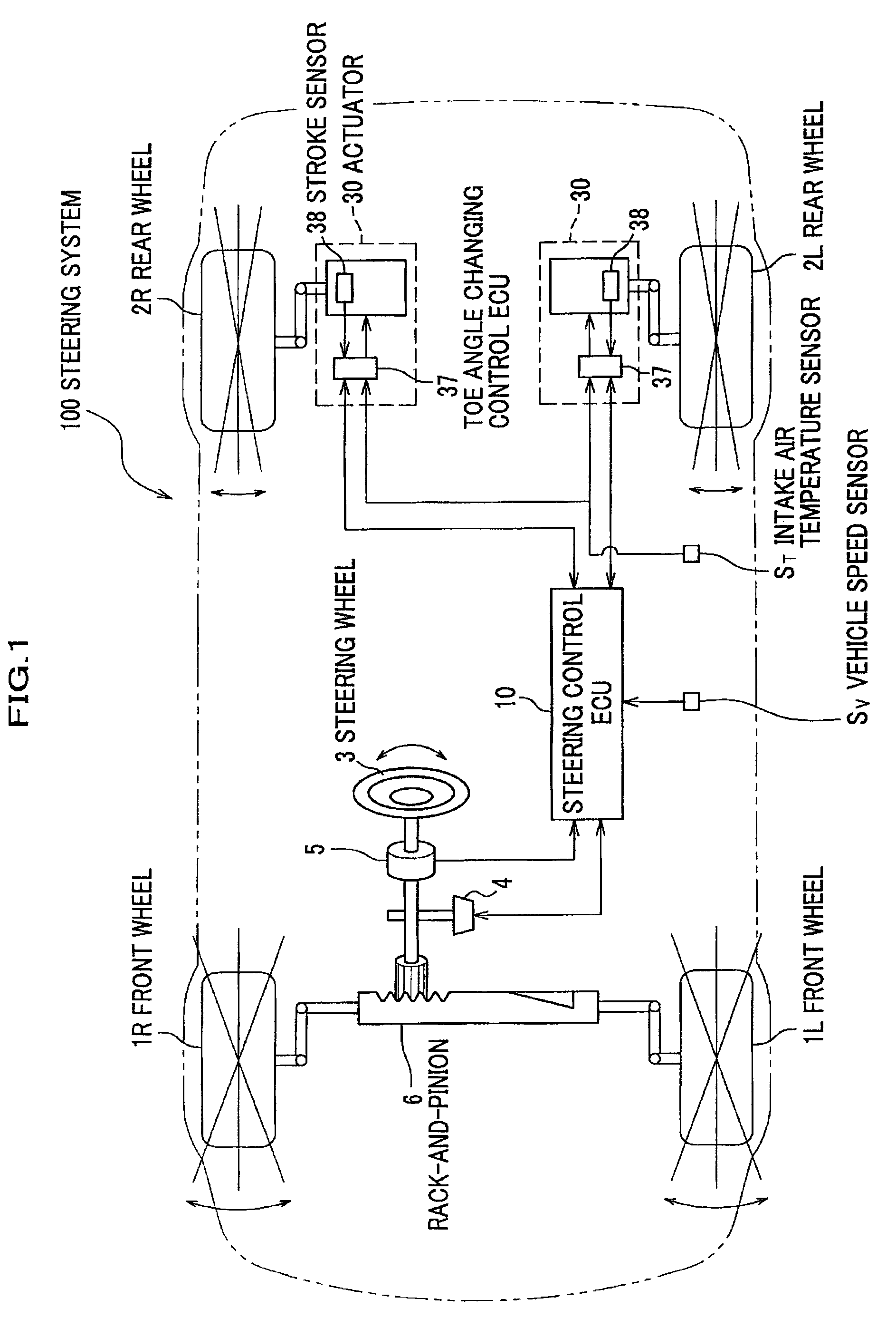
[0038]FIG. 1 is a view showing the construction of a steering system 100 having a toe angle changing control ECU according to the present embodiment. As shown in FIG. 1, the steering system 100 includes a front wheel steering system and a rear wheel steering system. The front wheel steering system steers left and right front wheels 1L, 1R in accordance with the operation of a steering handle 3. The rear wheel steering system steers left and right rear wheels 2L, 2R ...


PUM


Abstract

An alignment changing control device that includes: a motor drive section which adjusts electrical power supplied to a motor of the electric actuator according to an operation command and, when receiving an operation inhibiting signal, limits or stops supplying the electrical power to the motor; a motor temperature estimating section for calculating an estimated temperature of the motor from at least a current supplied to the motor, an outside air temperature and a vehicle speed, based on heat balance relationship; and a comparator which transmits the operation inhibiting signal to the motor drive section when the estimated temperature of the motor calculated by the motor temperature estimating section is higher than a predetermined temperature, which is equal to or lower than an operation allowable temperature of the motor.

Description

CROSS-REFERENCE TO RELATED APPLICATION(S)[0001]This application claims the foreign priority benefit under Title 35, United States Code, §119 (a)-(d), of Japanese Patent Application No. 2007-046459 filed on Feb. 27, 2007 in the Japan Patent Office, the disclosure of which is herein incorporated by reference in its entirety.BACKGROUND OF THE INVENTION[0002]1. Field of the Invention[0003]The present invention relates to an alignment changing control device for controlling electric actuators which change alignment angles of vehicle wheels.[0004]2. Description of the Related Art[0005]There is conventionally known four-wheel steering vehicles whose rear wheels are steered linking with the steering handle of the vehicle. For example, there is known an all-wheel independent steering device for independently controlling the operation of the alignment angles of all wheels according to the steering angle of the steering handle and the vehicle speed (see Japanese Patent Publication No. Hei 6-47...

Claims


Application Information

Patent Timeline
Patent Type & Authority Patents(United States)
IPC IPC(8): B62D5/06B62D5/04B62D6/00B62D7/08B62D7/15B62D113/00B62D119/00H02P29/00
CPCB60G7/006B62D5/0481B62D5/0496B62D7/146B62D17/00B60L15/20B60G2200/10B60G2200/18B60G2200/462B60G2200/4622Y02T10/7275Y02T10/72Y02T10/64
Inventor HORIUCHI, YUTAKASUGITANI, NOBUO
Owner HONDA MOTOR CO LTD
Learn More