Rotary electric apparatus having rotor with field winding inducing current therethrough for generating magnetic field
a rotary electric and field winding technology, which is applied in the direction of motor/generator/converter stopper, electric generator control, dynamo-electric converter control, etc., can solve the problem of large ripples in the generated torque (torque ripples), and achieve the effect of preventing an increase in the magnetic resistance of the rotor cor
- Summary
- Abstract
- Description
- Claims
- Application Information
AI Technical Summary
Benefits of technology
Problems solved by technology
Method used
Image
Examples
first embodiment
Referring to FIGS. 1-19, a rotary electric apparatus according to a first embodiment of the present invention will now be described.
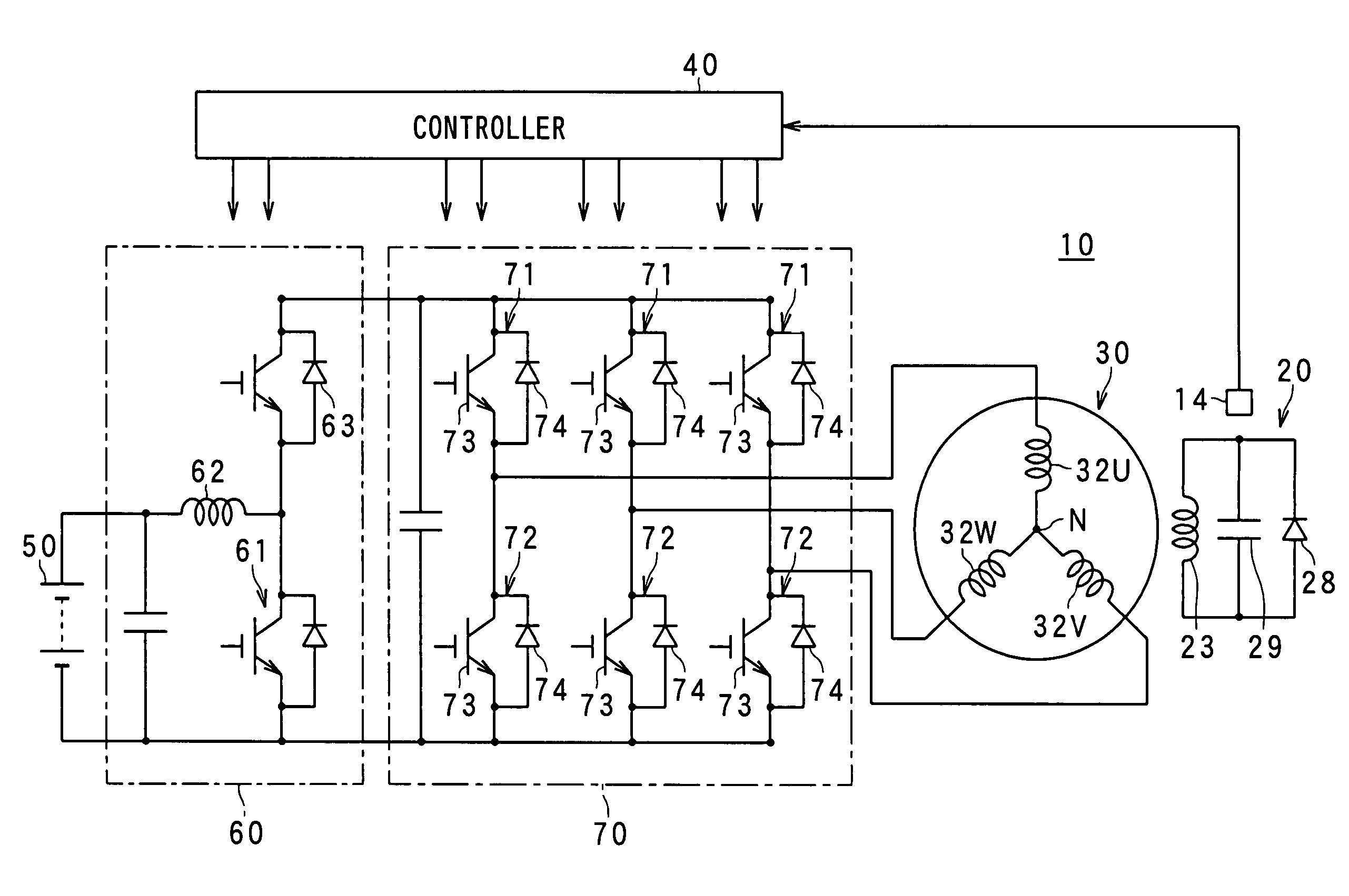
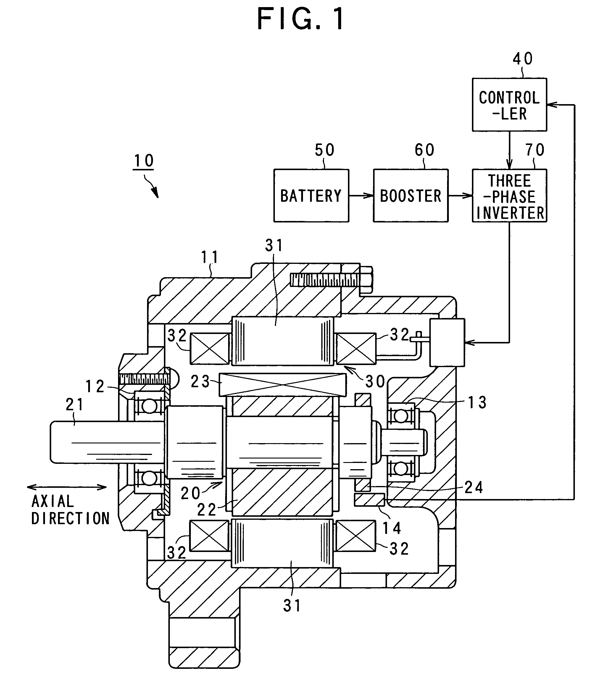
FIG. 1 shows the configuration of a rotary electric apparatus according to the present invention. The rotary electric apparatus includes a “synchronous motor (which is a field winding type of synchronous motor)”10 according to a first embodiment. As shown, the synchronous motor 10 is equipped with a housing 11, a rotor 20, and a stator 30.
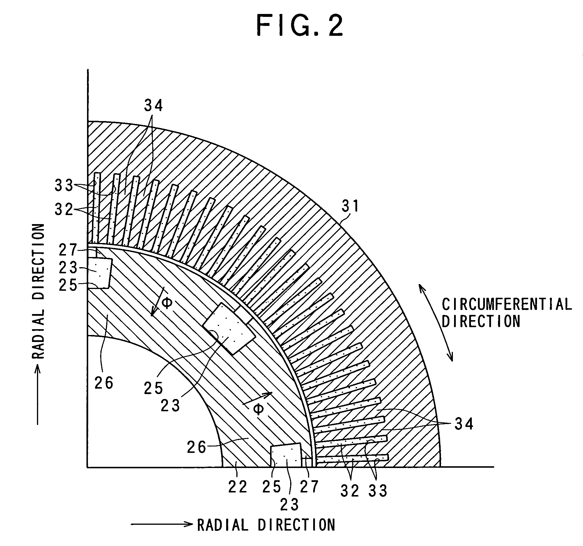
Of these components, the rotor 20 is provided with a shaft 21, a rotor core 22, and a rotor coil 23. The shaft 21 is rotatably supported to the housing 11 with a pair of bearings 12 and 13. The shaft 21 is a cylindrical member having a predetermined length along which an axial direction can be defined, whereby a radial direction can be defined as directions perpendicular to the axial direction and a circumferential direction around the shaft 21 (refer to FIGS. 1 and 2). These primary directions can also be defined as t...
modification 1-1
In the foregoing first embodiment, the first voltage from the battery 50 is boosted up to the second voltage V2 by the booster 60, and the second voltage V2 is used to drive the inverter 70. In this regard, there is provided another form. As shown in FIG. 20, an electrical switch 80 is provided so as to receive the output voltages from both the battery 50 and the booster 60. This switch 80 is subjected to switching operations to properly select the output from the battery 50 or the booster 60 in a controlled manner to drive the inverter 70. Specifically, the switch 80 includes first and second on / off electrical switches 81 and 82. When the first switch 81 is turned on and the second switch 82 is tuned off, it is possible to drive the inverter 70 at the first voltage V1 from the battery 50. In contrast, turning off the first switch 81 and turning on the second switch 82 makes it possible to drive the inverter 70 at the second voltage V2 outputted from the booster 60. When applying th...
modification 1-2
In the above modification, the switch 80 is used to perform the selective switching actions between the battery 50 or booster 60 and the inverter 70. However, this switching configuration may be modified into that shown in FIG. 21. Specifically, the battery 50 is replaced by a first DC power supply 51 whose rated value is set to the first voltage V1 and a second DC power supply 52 whose rated value is set to the second voltage V2 higher than the first voltage V1. The switch 80 is still arranged to selectively select and supply the outputs of the first and second DC power supplies 51 and 52 to drive the inverter 70. Thus the similar advantages to those in the foregoing modification can be gained.
PUM
 Abstract
Description
Claims
Application Information
 - R&D
- Intellectual Property
- Life Sciences
- Materials
- Tech Scout
- Unparalleled Data Quality
- Higher Quality Content
- 60% Fewer Hallucinations
Browse by: Latest US Patents, China's latest patents, Technical Efficacy Thesaurus, Application Domain, Technology Topic, Popular Technical Reports.
© 2025 PatSnap. All rights reserved.Legal|Privacy policy|Modern Slavery Act Transparency Statement|Sitemap|About US| Contact US: help@patsnap.com


